
Table of Contents
Introduction
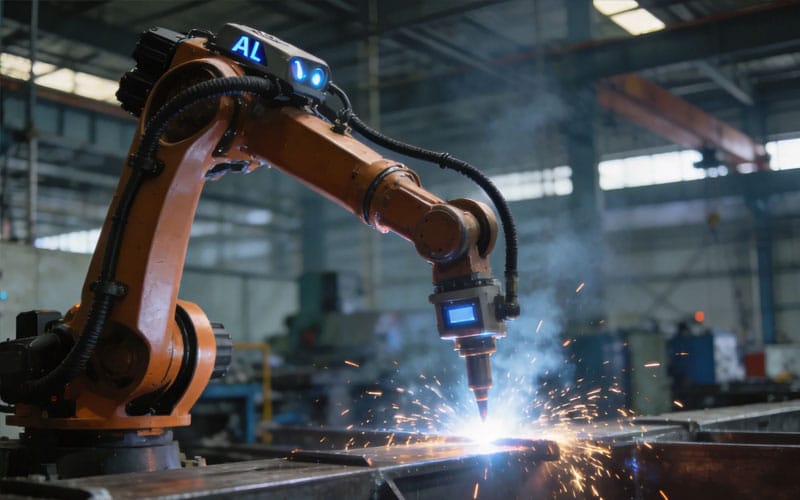
A robotic welding cell is much more than a robot holding a welding torch. In a well-designed system, the robot, welding equipment, fixtures, positioners, sensors, safety devices, and control software work together as one coordinated production unit.
That distinction matters because many automation projects are evaluated too narrowly. If you focus only on robot reach or welding speed, you may overlook the factors that determine whether the entire process can repeat reliably. Part positioning, joint variation, loading time, fixture stability, torch access, welding sequence, and sensing can all influence the final result.
For manufacturers considering welding automation, understanding how a robotic welding cell works helps answer a more useful question: not simply whether a robot can perform a weld, but whether the complete production process can be organized around repeatable and controllable conditions.
What Is a Robotic Welding Cell?
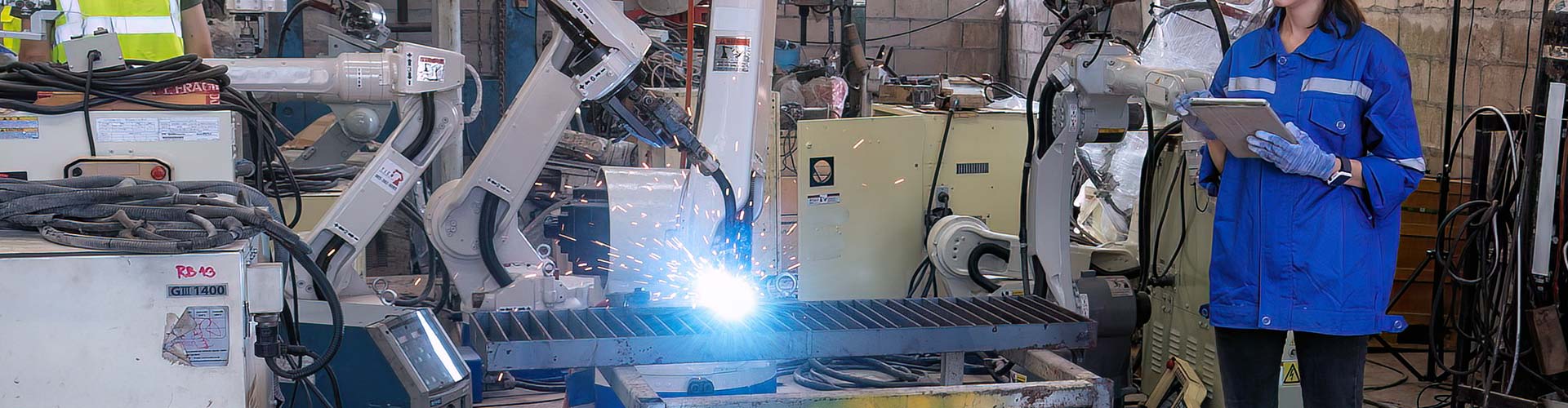
A robotic welding cell is an integrated workstation in which an industrial robot performs welding operations within a controlled production environment. Depending on the application, the cell may also include a welding power source, torch system, wire feeder, workpiece fixture, positioner, seam sensor, controller, safety enclosure, and material-handling equipment.
The robot provides repeatable motion, but the cell as a whole provides the process structure.
This is why two robotic welding cells using similar robots can perform very differently. One may handle a simple flat component with fixed joints, while another may weld a large three-dimensional structure that requires coordinated positioner movement, seam recognition, and multiple welding orientations.
A robotic welding cell should therefore be understood as a complete process system rather than a standalone machine.
The Main Components of a Robotic Welding Cell
Every robotic welding cell is configured around the workpiece and welding process, but several components appear in most industrial systems.
| Component | Main Function | Why It Matters |
|---|---|---|
| Welding robot | Moves the torch along the programmed path | Provides repeatable motion and torch orientation |
| Welding power source | Controls the welding process | Maintains the required welding parameters |
| Welding torch | Delivers the arc to the joint | Torch geometry affects access and collision clearance |
| Wire feeder | Supplies filler wire when required | Stable feeding supports consistent welding |
| Fixture | Locates and clamps the workpiece | Establishes repeatable part position |
| Positioner | Rotates or tilts the workpiece | Improves weld access and welding orientation |
| Seam sensing system | Detects actual joint position | Helps manage normal workpiece variation |
| Robot controller | Executes motion and process commands | Coordinates robot movement and welding sequence |
| PLC or cell controller | Coordinates the complete workstation | Connects robots, fixtures, safety devices, and auxiliary equipment |
| Safety system | Controls access to the operating area | Protects personnel during automated operation |
The important point is that these components are interdependent.
A highly repeatable robot cannot compensate for a fixture that locates parts differently every cycle. A good fixture cannot solve a torch-access problem. A seam sensor cannot correct every dimensional error if the workpiece itself falls outside the process limits.
The design must therefore be considered as one system.
How a Robotic Welding Cell Works
The exact sequence depends on the application, but most robotic welding cells follow a similar operating logic.
Workpiece Loading and Location
The process begins when the workpiece enters the cell and is placed into a fixture or positioning system.
At this stage, repeatability is already being established. The robot assumes that the component will appear in a predictable location or within a variation range that the sensing system can manage.
If a fixture allows the workpiece to shift between cycles, the welding path may no longer align with the actual joint.
For this reason, good fixture design is not simply about holding a component securely. It must create a consistent geometric relationship between the part and the robot.
Part Verification and Seam Detection
Once the component is located, the system may verify that the correct workpiece is present and that it is positioned appropriately.
Simple robotic welding cells may depend entirely on fixed programming. More flexible systems can use touch sensing, laser seam tracking, vision, or 3D scanning to locate joints before welding begins.
This becomes increasingly valuable when manufacturing tolerances create small differences between nominal CAD geometry and the actual fabricated part.
The sensor does not make uncontrolled variation acceptable. Instead, it gives the automation system more information about variation that exists within an expected operating range.
Welding Path Execution
After the system confirms the required position, the robot moves the torch along the welding path.
The controller coordinates robot speed, torch angle, welding parameters, arc start, arc stop, and any required transitions between seams.
For a simple workpiece, the robot may complete several fixed welds in sequence. For more complex parts, the cell may coordinate robot movement with a rotary or multi-axis positioner.
This coordinated motion is especially important when weld quality depends on maintaining a suitable torch orientation.
Repositioning the Workpiece
Many parts cannot be welded completely from one orientation.
A positioner can rotate, tilt, or index the workpiece so the robot can access joints that would otherwise require difficult torch angles.
This is one of the most important differences between designing a robot program and designing a robotic welding cell.
The question is not only:
Can the robot reach the seam?
A better question is:
Can the complete system present the seam to the robot in a stable and weldable orientation?
Sometimes moving the workpiece is more effective than forcing the robot into an awkward wrist configuration.
Completion and Unloading
After welding is completed, the system ends the welding cycle and allows the workpiece to be removed.
In more integrated production lines, unloading may be connected with automated material handling, inspection, or the next manufacturing operation.
The complete cycle therefore includes much more than arc time.
This is essential when evaluating cell performance.
A robot that welds quickly but waits for slow manual loading may not improve overall production as much as expected. The performance of a robotic welding cell should be evaluated from workpiece entry to workpiece exit.
The Three Layers of Repeatability in Robotic Welding
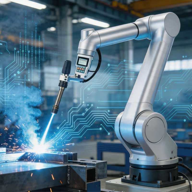
One useful way to understand robotic welding cell performance is to separate repeatability into three layers.
The first is part repeatability.
The component must arrive at the welding station with dimensions, joint location, and fit-up that remain within controlled limits.
The second is motion repeatability.
The robot must reproduce the intended torch path and orientation consistently.
The third is process repeatability.
The welding parameters, wire feeding, shielding conditions, welding sequence, and other process variables must remain stable enough to reproduce the required weld.
A robotic welding cell performs best when all three layers support one another.
If motion repeatability is strong but part repeatability is poor, the robot may follow the correct program along the wrong joint location.
If the part and robot are both repeatable but the welding process is unstable, weld results can still vary.
This three-layer model is useful because it prevents automation problems from being blamed automatically on the robot.
Why Fixture Design Is Critical
Fixtures are sometimes treated as supporting equipment, but in robotic welding they are part of the automation strategy.
A skilled manual welder can often notice that a component has shifted slightly and adapt torch movement. A robot following a fixed path cannot make that judgment unless the cell includes a sensing method that detects the change.
The fixture therefore creates the physical reference system on which the program depends.
Good fixture design should locate the workpiece consistently, provide adequate clamping, maintain torch access, minimize unnecessary obstruction, and account for how the part may respond to welding heat.
Clamping force also requires balance.
Too little restraint may allow movement. Excessive or poorly distributed restraint can influence distortion or make loading unnecessarily difficult.
The best fixture is not simply the strongest one. It is the fixture that supports repeatability without creating new process problems.
The Role of Positioners in a Robotic Welding Cell
Positioners allow the workpiece to move while the robot remains within a more favorable working range.
This can improve torch access, reduce extreme wrist angles, and help maintain suitable welding orientation.
For large frames, tanks, fabricated structures, machinery components, and other three-dimensional assemblies, the positioner may be just as important as the robot itself.
A robot may technically be able to reach a weld while still approaching it from an unsuitable angle. Positioning the workpiece differently can often produce a more stable welding path.
When the positioner and robot are coordinated through the same control system, their motion can also be synchronized.
This allows the system to follow curved or circumferential seams that would be difficult to complete through robot movement alone.
How Seam Tracking Improves Cell Flexibility
Fixed-path robotic welding works best when joint locations are highly repeatable.
Real fabricated components often contain some variation.
Plate dimensions, forming, cutting, assembly, tack welding, and fixture loading can all influence where the actual joint appears.
Seam sensing helps bridge the gap between nominal geometry and the real workpiece.
Depending on the process, the system may identify the seam before welding or track it during welding. The resulting information can be used to correct the path within defined limits.
This is particularly useful for robotic welding cells intended to handle larger structures or several product variants.
However, sensing should not be used as an excuse to accept uncontrolled manufacturing variation.
A more reliable approach is:
control the variation that can reasonably be controlled, then use sensing to manage the remaining predictable variation.
That creates a much more stable production system.
Robotic Welding Cells for High-Mix Production
Traditional automation is easiest when production consists of large numbers of identical parts.
High-mix manufacturing creates a different challenge because workpieces, seam locations, and welding sequences may change regularly.
Modern robotic welding cells can address this through flexible fixtures, reusable programs, offline programming, part recognition, seam sensing, and teach-free welding technology.
Instead of manually teaching every point for every new component, the system may use workpiece geometry and sensor information to reduce programming effort.
This does not mean that every highly variable application can be automated efficiently.
The key is whether the differences between products are structured.
If a product family uses similar joint types, repeatable datums, predictable geometry, and known welding procedures, a flexible cell may handle multiple variants much more effectively than a traditional fixed-purpose system.
This is why high-mix automation should be designed around product families rather than isolated components.
Robot Selection Should Follow Process Analysis
A common mistake is selecting the robot first and designing the process around it later.
A stronger approach begins with the workpiece.
Engineers should first examine part dimensions, weld joint locations, torch access, welding process, payload requirements, reach, expected cycle flow, fixture geometry, and whether external axes are needed.
Only then should the robot configuration be selected.
For example, a long component may require a robot mounted on a linear axis. A heavy structure may need a large positioner. A deeply recessed weld may require different torch geometry. A cell handling multiple product types may benefit from additional sensing.
The robot is therefore one result of the system design process, not the starting point.
SHUIPO’s welding automation products and robotic systems reflect this system-based approach, where welding equipment, robot motion, workpiece positioning, and production requirements must be coordinated around the application.
Safety in a Robotic Welding Cell
Automation changes the nature of welding-related risks, but it does not eliminate the need for safety engineering.
A robotic welding cell must control access to moving equipment and active welding operations. Depending on the design, this may involve fencing, interlocked doors, light curtains, safety scanners, emergency stops, safe robot functions, and controlled operating modes.
The welding process itself also introduces arc radiation, heat, fumes, spatter, and electrical risks.
Safety design should therefore consider both robot motion and welding conditions.
The correct strategy depends on the cell configuration, operating mode, loading method, and degree of human interaction.
Safety should be designed into the cell from the beginning rather than added after the mechanical layout has already been finalized.
Why Cycle Time Should Be Measured at Cell Level
Robot speed is only one part of production performance.
Imagine a robotic welding cell where the robot completes the required welding quickly, but loading, clamping, repositioning, and unloading take much longer.
Improving robot movement further will have little effect because the bottleneck has moved elsewhere.
This is why complete cell cycle time should be analyzed.
The full sequence includes workpiece loading, fixture closing, part verification, seam sensing, welding, repositioning, cleaning if required, fixture release, and unloading.
Understanding these steps helps identify where automation creates the greatest improvement.
In some cases, the welding operation is the main bottleneck. In others, the largest opportunity may lie in fixture design, material handling, or workpiece positioning.
A strong robotic welding project therefore optimizes the entire cycle rather than only arc-on performance.
When a Robotic Welding Cell Is a Good Fit
A robotic welding cell is especially suitable when the manufacturing process contains repeatable welding tasks and the workpieces can be positioned within controlled limits.
Good candidates often include products with recurring joint locations, repeated welding sequences, accessible seams, and relatively stable part families.
The cell becomes even more valuable when weld consistency needs to remain stable across repeated production cycles.
Applications with substantial variation can also be suitable if that variation can be measured and managed through sensing, flexible fixtures, or adaptive programming.
The important distinction is between controlled variation and unpredictable variation.
Controlled variation can often be automated.
Unpredictable variation may still require greater human judgment or upstream process improvement.
Common Robotic Welding Cell Design Mistakes
One common mistake is assuming that robot accuracy automatically solves poor fit-up.
It does not.
Another is ignoring torch access until late in the design process. A robot may reach the general work area while still being unable to maintain the correct torch angle around fixtures or adjacent features.
Fixture design can also be underestimated. If the workpiece does not repeat, the robot program cannot repeat relative to the joint.
Another frequent mistake is optimizing individual welding movements without considering loading and unloading.
This can create a technically impressive robot program inside an inefficient production cycle.
Finally, some cells are designed only around today’s component.
If future product variation is likely, modular fixtures, sensing capability, adaptable programming, and suitable positioner capacity should be considered earlier.
These factors can determine whether a robotic welding cell remains useful as production requirements evolve.
How to Evaluate a Robotic Welding Cell Before Implementation
A useful evaluation begins with representative production parts rather than specially prepared demonstration components.
The workpieces used for testing should reflect normal tolerances, joint fit-up, surface condition, and assembly variation.
The evaluation should then consider whether the cell can locate the parts consistently, reach every required seam, maintain practical torch orientation, complete the required welding sequence, and manage expected variation.
It should also examine the interaction between different operations.
Does rotating the workpiece improve welding access? Can the fixture hold the part without obstructing the torch? Does sensing add value at specific joints? Are there areas where manual welding should remain part of the process?
These questions produce a more realistic automation plan than simply asking whether a robot is technically capable of welding the component.
The Future of Robotic Welding Cells
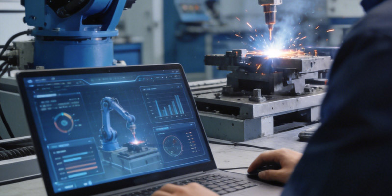
The direction of robotic welding is moving toward cells that require less manual programming and can respond more effectively to workpiece variation.
3D vision, automatic seam recognition, digital models, adaptive path correction, and teach-free programming are expanding the types of production that can be automated.
This is especially important for manufacturers that do not produce the same component continuously.
Future flexibility will depend less on teaching every robot point manually and more on giving the system enough information to understand where the workpiece is, where the joint is, and how the validated welding process should be applied.
Even as sensing and software become more capable, the fundamentals remain unchanged.
Part quality, fixture design, welding engineering, access, and process stability still determine whether automation can deliver repeatable results.
The most capable robotic welding cell is therefore not the one with the most technology. It is the one in which each technology solves a clearly defined production problem.
Conclusion
A robotic welding cell is a coordinated manufacturing system built around repeatability, controlled motion, stable welding processes, and reliable workpiece handling.
The robot is important, but it is only one part of the system.
Fixtures establish part location. Positioners create better welding orientations. Sensors help manage normal variation. Controllers coordinate the sequence. Safety systems control human interaction. Welding equipment maintains the process itself.
The strongest robotic welding cells are designed around the complete production cycle.
Before selecting equipment, manufacturers should understand their workpieces, joint variation, fixture requirements, weld accessibility, production flow, and future product changes.
When these factors are considered together, a robotic welding cell can provide a stable platform for consistent and scalable welding automation.
FAQ
What does a robotic welding cell include?
A robotic welding cell normally includes a welding robot, welding power source, torch, fixture, controller, safety system, and often a positioner or seam sensor. The exact configuration depends on the workpiece, welding process, joint accessibility, and required level of automation.
How does a robotic welding cell find the weld seam?
A fixed-path cell relies on consistent workpiece positioning, while more flexible systems can use touch sensing, laser tracking, vision, or 3D scanning. These technologies identify joint position and allow the robot to correct its path within defined process limits.
Can one robotic welding cell handle different products?
Yes, when the cell is designed for flexibility. Product families with predictable geometry can use interchangeable fixtures, multiple programs, vision sensing, and teach-free methods. Very large or uncontrolled differences between parts may still require separate setups or manual work.
Why are fixtures important in robotic welding cells?
Fixtures establish the reference position between the robot and the workpiece. If a part moves between cycles, the programmed welding path may no longer align with the joint. A good fixture supports consistent location, clamping, torch access, and repeatable production.
Is seam tracking necessary for every robotic welding cell?
No. Highly repeatable parts may work well with fixed robot paths. Seam tracking becomes more valuable when normal manufacturing tolerances cause the actual joint position to vary. The decision should be based on measured workpiece variation rather than added technology alone.
Need Help Choosing the Right Robotic Welding Cell?
If you’re unsure how a robotic welding cell should be configured for your workpieces, welding process, fixtures, positioners, or sensing requirements, our team can help evaluate the complete production workflow. Contact SHUIPO for a technical consultation and identify an automation approach that fits your actual welding conditions.