
Table of Contents
Introduction
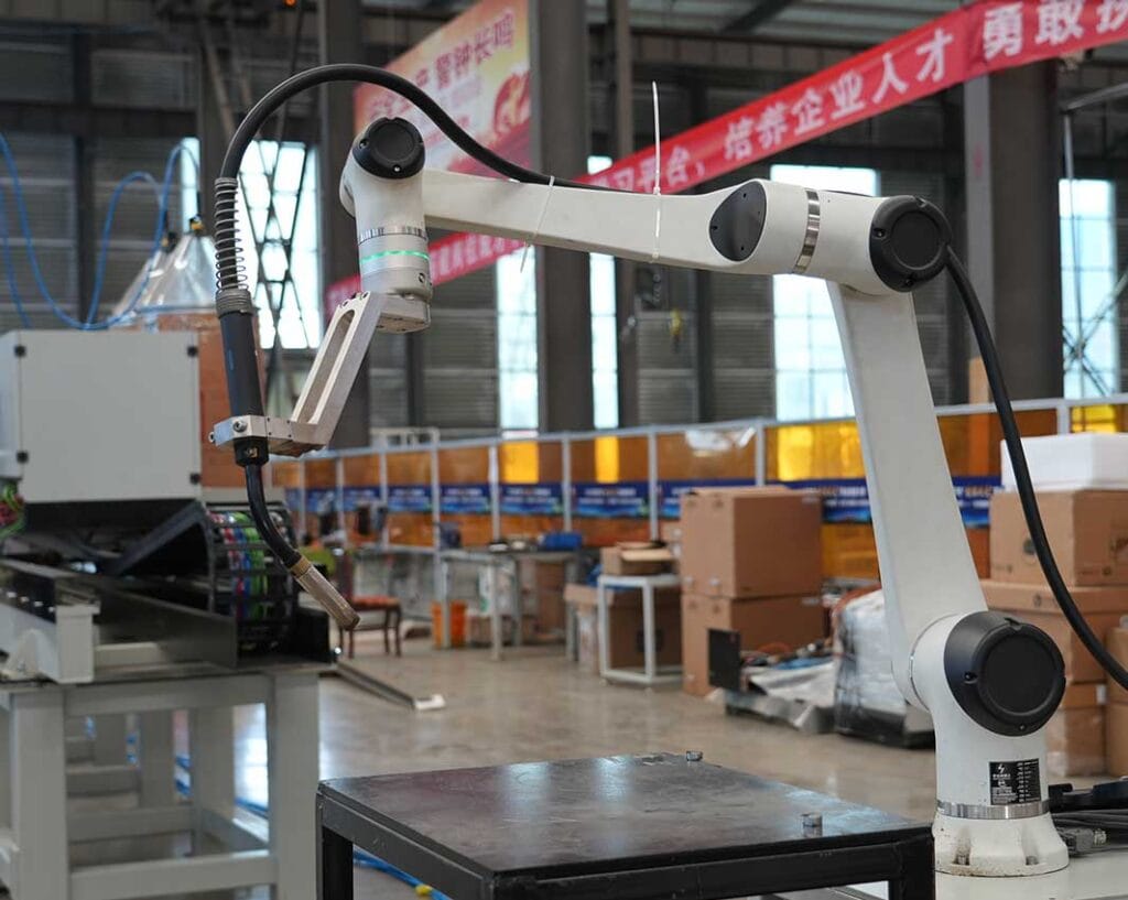
A robotic welding arm is one of the most visible parts of a welding automation system, but its performance cannot be judged by reach, payload, or movement speed alone. The arm must place the welding torch in the correct position, maintain a suitable angle to the joint, move smoothly through the programmed path, avoid collisions, and work with fixtures, positioners, sensors, welding equipment, and safety devices.
This is why selecting a robotic welding arm should begin with the workpiece rather than with the robot specification sheet.
A compact component with welds on several faces may require strong wrist flexibility but only moderate reach. A long fabricated structure may need a robot mounted on a linear axis. A heavy torch package can increase payload and wrist-moment requirements, while high-mix production may make programming flexibility and sensing more important than maximum speed.
The right robotic welding arm is therefore the one that fits the complete welding process. This guide explains the major technical factors that influence robot selection, how arm configuration affects welding performance, and what manufacturers should evaluate before integrating a robot into an automated welding system.
What Is a Robotic Welding Arm?
A robotic welding arm is a programmable multi-axis manipulator used to position and move a welding torch along a defined welding path.
Most industrial welding applications use articulated robots derived from the broader category of the industrial robot. Their multiple rotary joints allow the robot to change both tool position and orientation while moving around complex workpieces.
A typical robotic welding arm operates together with several other components:
- welding torch
- welding power source
- wire feeder
- robot controller
- fixture
- workpiece positioner
- seam sensing system
- safety equipment
- cable management system
The arm supplies controlled motion, but it does not create a successful welding process by itself.
A robot can follow a programmed path accurately while still producing poor results if the workpiece is positioned incorrectly, the seam moves outside the expected location, the torch cannot maintain the required angle, or the welding parameters are unsuitable.
This distinction is fundamental when planning industrial welding automation.
Why Six-Axis Arms Are Common in Robotic Welding
Six-axis articulated robots are widely used for welding because welding rarely involves position alone.
The torch also needs the correct orientation.
The first robot axes generally create the larger movement required to reach different areas of the workpiece, while the wrist axes provide finer orientation control around the weld.
That combination allows a robotic welding arm to approach joints from different directions and follow three-dimensional geometry.
Six-axis motion is particularly useful for:
- frames
- brackets
- machinery structures
- tanks
- curved components
- pipe assemblies
- multi-sided fabrications
- components containing joints at several orientations
The flexibility is valuable, but it creates another engineering challenge.
A robot may be physically capable of reaching a joint while entering an awkward wrist configuration that makes the welding path unstable or increases collision risk.
Robot reach therefore needs to be evaluated together with orientation.
The Main Factors When Selecting a Robotic Welding Arm
Robot selection should connect directly to the welding process.
| Selection Factor | Why It Matters | Common Risk if Overlooked |
|---|---|---|
| Reach | Determines accessible workspace | Robot reaches the area but not the required torch orientation |
| Payload | Supports torch and mounted equipment | Tool package exceeds practical robot capacity |
| Wrist moment | Accounts for tool length and center of gravity | Excessive mechanical load on wrist axes |
| Axis configuration | Determines orientation flexibility | Difficult movement around complex joints |
| Repeatability | Supports consistent path execution | Reduced positional consistency |
| Working envelope | Defines usable welding area | Fixtures or parts block robot movement |
| Mounting position | Changes available workspace | Poor access to specific weld zones |
| External axes | Extend motion capability | Large parts exceed fixed robot range |
| Programming method | Affects setup and changeover | High-mix production becomes inefficient |
| Sensor compatibility | Supports path correction | Robot cannot manage normal joint variation |
These factors should not be evaluated independently.
A longer-reach robot, for example, may have different payload characteristics or may become less effective near the edge of its working envelope.
The complete application determines the best balance.
Robot Reach Is More Than Maximum Distance
Robot reach is one of the first specifications manufacturers compare, but maximum reach can be misleading.
A manufacturer may see that the farthest joint is 1.8 meters from the robot base and choose an arm with slightly more than 1.8 meters of published reach.
Geometrically, that seems sufficient.
In practice, the robot may need additional space to maintain the correct torch angle. The fixture may block one approach direction. The robot wrist may rotate toward its joint limit, or cables may interfere with the workpiece.
The usable welding envelope is therefore smaller and more complex than a simple circle around the robot base.
A stronger evaluation considers:
- real torch length
- torch orientation
- fixture geometry
- surrounding structures
- wrist movement
- robot joint limits
- cable clearance
- workpiece position
The goal is to keep important welding paths inside a comfortable part of the robot’s operating range rather than repeatedly forcing the arm to its physical limits.
Payload and Wrist Moment Matter in Welding
Payload is another specification that can be misunderstood.
The welding torch may not appear especially heavy, but the complete robot-mounted package can include:
- torch
- collision sensor
- seam sensor
- camera or laser sensor
- mounting bracket
- cable connections
- wire-related components
The robot needs to support the entire tool package.
More importantly, weight distribution matters.
A long torch assembly creates a different mechanical load from a compact tool of the same mass because the center of gravity sits farther away from the robot wrist.
This creates a larger moment.
For that reason, robotic welding arm selection should consider both payload and the center of gravity of the actual end-of-arm equipment.
Ignoring this can produce a system that appears acceptable according to total weight but operates near undesirable mechanical limits during real welding movement.
Torch Orientation Can Matter More Than Reach
In welding automation, reaching the joint is only half the requirement.
The torch must reach it correctly.
Joint geometry determines appropriate torch orientation, travel direction, and working angle. These conditions can change continuously through curved or three-dimensional seams.
This becomes particularly important when a workpiece contains joints:
- inside corners
- behind structural members
- near fixture clamps
- around curved surfaces
- on opposite faces
- inside partially enclosed structures
A robotic welding arm must maintain enough wrist freedom to follow these joints without creating abrupt movement.
This is why simulation is valuable before equipment is finalized.
A digital model can show whether a proposed robot can reach all seams while maintaining appropriate tool orientation and avoiding collisions.
How Robot Mounting Changes the Working Envelope
A robotic welding arm does not always need to stand on the floor beside the workpiece.
Mounting position can significantly change access.
Common configurations include:
- floor-mounted
- elevated pedestal-mounted
- wall-mounted
- inverted or overhead-mounted
- rail-mounted
Each arrangement creates a different working envelope.
A floor-mounted robot may provide simple integration for compact workpieces. An elevated pedestal can improve access to taller structures. Overhead mounting can free floor space and provide better access to some large assemblies.
Rail mounting adds another dimension.
Instead of relying only on arm reach, the entire robot can travel along a linear axis.
This can be particularly useful when welding long structures because the robot can remain within a favorable working range while moving between welding zones.
The best mounting configuration should therefore follow workpiece geometry rather than workshop habit.
When a Linear Axis Becomes Necessary
A fixed robotic welding arm works well when all required joints fall inside its usable workspace.
Long workpieces create a different situation.
If seams are distributed across several meters, simply selecting a very long robot arm may not produce the best welding geometry.
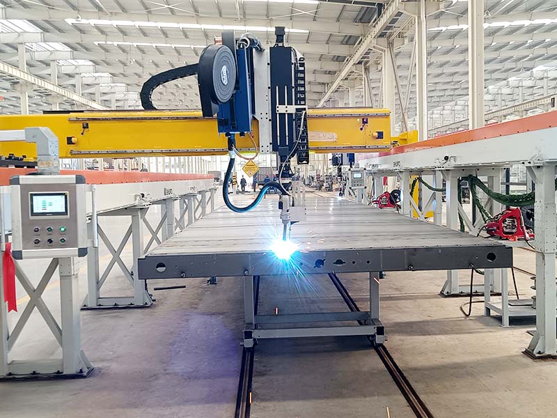
A linear track can move the robot along the length of the workpiece.
This creates several advantages:
- larger effective working range
- reduced extreme arm extension
- better torch orientation
- easier access to multiple welding zones
- more consistent robot posture
The linear axis effectively becomes another controlled robot axis.
However, additional motion also increases programming complexity.
Engineers need to determine when the track should reposition between welds and when coordinated motion between the robot and track is beneficial.
For long fabricated structures, this system-level planning is often more important than selecting the arm with the greatest standalone reach.
Why Workpiece Positioners Reduce Arm Complexity
Another way to expand robot capability is to move the workpiece instead of the robot.
A positioner can rotate or tilt the component so that the weld is presented to the robotic welding arm from a more favorable direction.
This is especially valuable for:
- cylindrical parts
- frames
- multi-sided assemblies
- long curved joints
- circumferential seams
- heavy fabricated components
Without a positioner, the robot may need to reach underneath the component or rotate its wrist into an extreme configuration.
With a positioner, the same joint can sometimes be moved into a more accessible orientation.
This often produces smoother robot motion.
In more advanced cells, the robot and positioner move in coordination. A circumferential seam, for example, may be completed through controlled workpiece rotation while the robot maintains a stable torch relationship.
Moving the part can therefore be as important as moving the arm.
Fixture Design Directly Affects Robotic Arm Accuracy
Robotic welding arms are valued for repeatable motion, but that repeatability only creates value when the workpiece repeats as well.
If a fixture locates one component differently from the next, the robot can follow exactly the same path while the real weld seam has moved.
This is especially important for fixed-path welding.
A good fixture should:
- establish reliable locating references
- hold the component consistently
- maintain torch access
- avoid unnecessary robot interference
- allow practical loading
- consider welding distortion
Fixture design and robot path design should therefore happen together.
A clamp placed in the wrong location can block an otherwise ideal welding approach.
Similarly, a fixture that requires the robot to reach deep around structural members may reduce effective workspace even when the workpiece itself appears compact.
The robot, fixture, and component should be treated as one geometric system.
How Seam Sensing Expands Arm Capability
A robotic welding arm repeats its programmed motion extremely well, but real fabricated components can contain variation.
Cutting, forming, assembly, tack welding, and fixture loading can shift the actual seam away from its nominal position.
Sensing gives the robot additional information about the real workpiece.
A system may use:
- touch sensing
- laser seam tracking
- vision
- 3D sensing
- other joint-detection methods
The objective is not to change the fundamental capabilities of the arm.
The objective is to determine where the arm should move.
This distinction matters.
Sensing does not give a short-reach robot more physical reach. It does not make an inaccessible joint accessible. It does not fix a welding torch that cannot fit between two components.
What it can do is help the existing robotic welding arm align its repeatable motion more accurately with the real weld location.
For applications with meaningful but controlled part variation, robotic welding systems can combine arm movement, workpiece positioning, and sensing within the same automated process.
Robotic Welding Arms for High-Mix Production
A robot arm designed for one repeated component can rely heavily on fixed programming.
High-mix manufacturing demands more flexibility.
When workpieces change regularly, programming time can become a significant part of the automation process.
Several factors become more important:
- simplified teaching
- offline programming
- reusable welding programs
- geometry-based programming
- sensing
- flexible fixtures
- teach-free methods
The robotic welding arm itself may be mechanically capable of handling many components, but the system is not truly flexible if every product change requires extensive manual reprogramming.
This is why high-mix robot selection should consider software and programming workflow alongside hardware specifications.
A technically capable arm with an inefficient programming process may create unnecessary production delays.
Robotic Welding Arm vs Collaborative Welding Arm
Collaborative robots are increasingly used in welding applications, but they should not automatically replace conventional industrial welding robots.
Both have strengths.
| Factor | Industrial Robotic Welding Arm | Collaborative Welding Arm |
|---|---|---|
| Motion speed | Often designed for faster industrial operation | Often emphasizes controlled collaborative operation |
| Programming | Can require more specialist knowledge | Frequently designed for simplified teaching |
| Payload range | Broad range available | Often more limited |
| Workcell design | Common in dedicated cells | Often supports more flexible layouts |
| High-mix production | Strong with suitable programming and sensing | Often attractive for frequent changeover |
| Large structures | Can integrate effectively with rails and external axes | Depends heavily on reach and system layout |
| Safety | Complete cell requires safety engineering | Welding process still requires application-level protection |
The right choice depends on production requirements.
For highly repetitive production with demanding cycle requirements, a conventional industrial robot may be the stronger option.
For changing workpieces where programming and redeployment are important, a collaborative configuration may offer practical advantages.
Repeatability Is Not the Same as Welding Accuracy
This distinction is essential.
Robot repeatability refers to how consistently the arm can return to a programmed position.
Welding accuracy depends on whether that programmed position matches the real joint.
A robot may have excellent repeatability while the workpiece shifts several millimeters between cycles.
In that case, the robot is repeating accurately but welding inaccurately relative to the seam.
This is why the complete accuracy chain should be considered:
workpiece manufacturing → fixture location → sensor measurement → robot path → torch position.
Weakness anywhere in this chain can influence the final weld.
Robotic welding arm specifications should therefore never be evaluated separately from production tolerances.
Robot Speed Should Not Be the Main Selection Criterion
A faster arm does not automatically create a faster welding process.
Welding travel speed is determined primarily by the welding procedure, material, joint design, and required weld characteristics.
The robot often spends only part of the total production cycle performing rapid movement between joints.
Other time is used for:
- welding
- loading
- clamping
- sensing
- workpiece positioning
- cleaning
- unloading
Increasing robot movement speed has limited value if welding or handling remains the dominant cycle component.
Instead of asking which robot is fastest, manufacturers should ask where time is actually being consumed across the complete workcell.
That produces a more useful automation decision.
Cable Management Is Part of Arm Design
Cables and hoses are easy to overlook during early robot selection.
During real operation, however, the robotic welding arm may rotate through complex paths while carrying:
- welding cables
- wire feed connections
- sensor cables
- gas lines
- utility connections
Poor routing can restrict movement, increase wear, or create interference with the workpiece.
Complex wrist rotation is particularly important.
A robot path that looks acceptable in a simplified simulation may create cable twisting when the actual torch package is installed.
Cable routing should therefore be evaluated during path design.
The most elegant geometric robot movement is not useful if the welding package cannot follow it reliably over repeated cycles.
How Robot Configuration Affects Collision Risk
Robotic welding cells contain many potential collision objects:
- workpiece
- fixture
- positioner
- clamps
- table
- welding torch
- sensors
- nearby robots
- safety structures
Complex components can create narrow access areas where the robot wrist passes close to surrounding geometry.
Collision analysis is therefore necessary during cell development.
Importantly, engineers should analyze not only welding paths but also approach and exit movements.
The robot may complete the weld successfully but collide while repositioning to the next seam.
Stored safe positions and structured transitions between welding zones can reduce this risk.
Simulation provides a useful first check, while physical validation remains necessary during commissioning.
Dual-Arm and Multi-Robot Welding
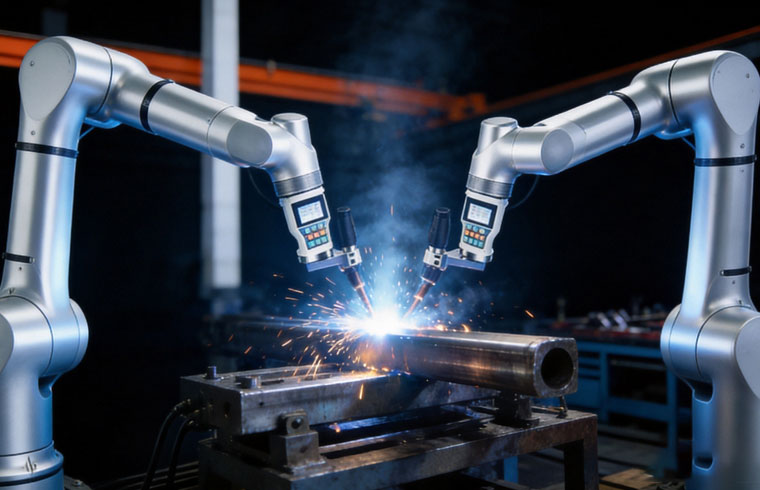
Some large components contain enough welding work to justify more than one robotic arm.
Two robots may work on different sides of a structure or divide a large number of seams between separate zones.
This can reduce excessive robot travel.
However, adding additional arms introduces new considerations:
- overlapping workspaces
- collision avoidance
- shared positioners
- welding sequence
- heat distribution
- fixture access
- cycle balance
Two robotic welding arms only improve productivity when the work can be divided logically.
If both robots constantly wait for the same positioning movement, the system may gain less than expected.
Multi-robot design should therefore begin with task allocation rather than robot quantity.
Common Robotic Welding Arm Selection Mistakes
One of the most common mistakes is choosing the arm based only on maximum reach.
Another is considering payload without calculating the tool center of gravity.
Manufacturers may also overlook real torch geometry and test robot access using only a simplified robot flange.
Another frequent problem is designing around one ideal component.
Normal production parts should be measured because real dimensional variation may change sensing or fixture requirements.
Selecting a robot before designing the workpiece position can also create unnecessary complexity.
Sometimes a smaller arm combined with a suitable positioner performs better than a larger robot attempting to reach every joint around a fixed component.
Finally, choosing the robot without considering future product families can limit the flexibility of the cell.
The best selection balances present requirements with realistic future production needs.
A Practical Robotic Welding Arm Selection Process
A structured evaluation can reduce many of these mistakes.
Step 1: Analyze the Workpiece
Document:
- overall dimensions
- weight
- weld locations
- joint geometry
- required orientations
- access restrictions
- expected variation
Step 2: Define the Welding Tool
Include the actual:
- torch
- bracket
- sensor
- collision device
- cable package
This establishes realistic payload and geometry.
Step 3: Determine Workpiece Movement
Decide whether the component should remain fixed or use:
- rotary positioner
- tilting positioner
- multi-axis positioner
- indexing table
Step 4: Evaluate Robot Reach and Orientation
Check the complete welding path, not individual points.
The robot should maintain suitable orientation without repeatedly approaching joint limits.
Step 5: Consider External Motion
Large workpieces may require a rail or other external axis.
Step 6: Analyze Variation
Determine whether fixture control is enough or whether seam sensing is required.
Step 7: Evaluate Programming Requirements
High-mix manufacturing may require more flexible programming than highly repetitive production.
Step 8: Validate the Complete Cell
Review loading, welding, positioning, unloading, safety, and maintenance access before finalizing the layout.
This sequence keeps equipment selection tied to the manufacturing problem.
The Role of a Robotic Welding Arm in Intelligent Welding
The next stage of robotic welding development is increasingly focused on giving the arm better information about the real workpiece.
Traditional robotic welding is based primarily on predefined trajectories.
More advanced systems combine robot motion with:
- 3D vision
- seam recognition
- path generation
- digital models
- adaptive correction
- workpiece identification
This changes the role of the arm.
The robot remains the motion platform, but the welding path can increasingly be generated or adjusted using information gathered from the component.
For high-mix manufacturing, this is especially significant.
The mechanical arm may already have enough reach and flexibility to weld several product families. The limitation has often been programming and the ability to handle joint variation.
Better sensing and programming methods help remove some of that limitation.
Why Bigger Is Not Always Better
Choosing a larger robotic welding arm can appear to provide more flexibility because it offers greater reach and payload.
But oversizing can introduce disadvantages.
A larger robot may:
- require more installation space
- create a larger safety area
- have different dynamic behavior
- reduce access around compact fixtures
- complicate cell layout
The objective should be appropriate capability, not maximum capability.
If a smaller arm covers the required workspace comfortably and a positioner presents joints effectively, that configuration may produce a simpler welding cell.
Likewise, a larger robot becomes useful when workpiece geometry genuinely requires the additional working range or payload.
Good engineering avoids selecting capacity that does not solve a real production requirement.
Future Trends in Robotic Welding Arms
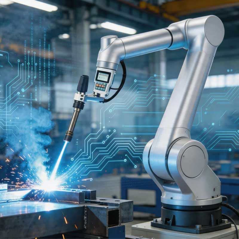
Robotic welding arms are becoming part of increasingly connected and adaptive production systems.
Mechanical improvements continue, but much of the important progress is happening in how robots are programmed and how they receive information.
Several developments are particularly relevant:
- simplified programming
- automated path generation
- 3D workpiece recognition
- intelligent seam detection
- adaptive welding
- offline simulation
- virtual commissioning
- multi-axis coordination
These developments reduce dependence on fixed point-by-point programming.
Future robotic welding arms will still need appropriate reach, payload, and motion capability, but their effectiveness will increasingly depend on how well they integrate with sensing and digital production information.
The best automation systems will combine mechanical capability with better understanding of the actual workpiece.
Conclusion
A robotic welding arm should be selected as part of a complete welding process, not as an isolated piece of equipment.
Reach determines where the robot can work, but torch orientation determines whether it can weld correctly. Payload matters, but tool center of gravity and wrist moment also need to be considered. Fixtures establish workpiece position, while positioners and external axes can simplify difficult robot movement.
For high-mix production, programming flexibility and sensing may become as important as mechanical specifications.
The strongest robotic welding arm configuration is therefore not necessarily the largest, fastest, or most complex.
It is the one that can reach the real joints, maintain suitable torch orientation, operate within a stable mechanical range, and integrate effectively with the workpiece, fixture, sensing, and production flow.
FAQ
What is a robotic welding arm?
A robotic welding arm is a programmable multi-axis manipulator that controls welding torch position and orientation. It normally works with a welding power source, fixture, controller, positioner, and sometimes seam sensing to create a repeatable automated welding process.
How much reach does a robotic welding arm need?
Required reach depends on workpiece dimensions, fixture geometry, torch length, and required welding angles. Maximum published reach alone is not enough because the robot must maintain suitable orientation and collision clearance throughout the complete welding path.
What payload is needed for a robotic welding arm?
Payload should include the complete tool package, including the torch, brackets, sensors, collision device, and related mounted equipment. Engineers should also evaluate the tool center of gravity and wrist moment rather than relying only on total tool weight.
Can a robotic welding arm handle large workpieces?
Yes. Large workpieces can be handled through suitable arm selection, linear robot tracks, workpiece positioners, or multi-robot layouts. The best configuration depends on joint distribution, workpiece movement, torch orientation, and the size of the required welding area.
Can one robotic welding arm weld different products?
Yes, when the cell is designed for flexible production. Stored programs, adjustable fixtures, seam sensing, positioners, offline programming, and geometry-based path generation can allow one robotic welding arm to handle multiple related product families efficiently.
Need Help Selecting the Right Robotic Welding Arm?
If your welding application involves complex joints, large workpieces, changing products, external axes, or seam variation, robot selection should begin with the actual component and welding process. A welding automation project consultation can evaluate arm reach, payload, positioning, fixtures, sensing, and workcell layout around your production requirements.