
Table of Contents
Introduction
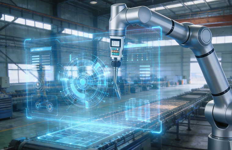
Robotic pipe welding is becoming increasingly important in manufacturing environments where pipe assemblies contain repeated joints, changing orientations, circumferential seams, branch connections, or tight access conditions. These applications demand more than simply moving a welding torch around a pipe.
A successful robotic pipe welding system must coordinate torch position, workpiece rotation, joint geometry, welding parameters, fixture accuracy, and sometimes seam sensing. When those elements are engineered as one process, automation can improve repeatability and make complex pipe joints much easier to manage across repeated production cycles.
The challenge is that pipe joints are rarely as simple as a straight weld on a flat plate. The torch angle changes continuously around curved surfaces, gravity influences the weld pool differently as orientation changes, and dimensional variation can shift the real seam away from the programmed path.
This article explains how robotic pipe welding manages those challenges, which joints are best suited to automation, and why sensing, positioners, fixtures, and process planning matter as much as the robot itself.
What Is Robotic Pipe Welding?
Robotic pipe welding uses an industrial robot or collaborative robot to control the welding torch around pipe joints according to programmed or sensor-adjusted paths.
Depending on the application, the robot may work with:
- fixed pipe assemblies
- rotating pipes
- multi-axis positioners
- circumferential joints
- branch connections
- curved pipe structures
- multiple pipe diameters
- repeated fabrication assemblies
The underlying welding process may vary. Robotic systems can be configured around different forms of arc welding, depending on material, joint design, production requirements, and required process control.
The important distinction is that robotic pipe welding is not defined only by the robot.
The complete system normally includes the robot, welding equipment, fixture, positioner, torch system, controller, and sometimes seam sensing or vision technology.
Why Pipe Welding Is More Difficult to Automate
A straight weld on a flat workpiece allows the torch to maintain a relatively stable orientation.
Pipe welding is different because the joint follows a curved surface.
As the robot travels around a pipe, the relationship between the torch and joint continuously changes. If the pipe is stationary, the robot wrist may need to rotate through a complex path. If the workpiece rotates, the robot and positioner must remain synchronized.
Several variables influence the process:
| Welding factor | Why it matters in robotic pipe welding |
|---|---|
| Pipe diameter | Changes the curvature and robot path |
| Joint type | Determines torch approach and welding sequence |
| Fit-up variation | Can shift the actual seam position |
| Torch angle | Must remain suitable as the joint changes direction |
| Workpiece orientation | Influences access and weld pool behavior |
| Positioner accuracy | Affects synchronization with robot movement |
| Fixture repeatability | Determines whether the joint appears where expected |
| Seam sensing | Helps compensate for controlled joint variation |
| Collision clearance | Becomes critical around curved assemblies |
These factors explain why robotic pipe welding should be designed around the entire joint geometry rather than simply around robot reach.
Circumferential Joints in Robotic Pipe Welding
Circumferential joints are among the most natural applications for robotic pipe welding.
The weld follows the circumference of the pipe where two cylindrical components meet. The system can approach this in two basic ways.
One method keeps the pipe stationary while the robot moves the torch around the joint.
The other rotates the pipe while the robot maintains a more stable welding position.
For many applications, rotating the workpiece provides a more controlled arrangement because the robot does not need to move through an extreme circular path.
A positioner can rotate the pipe at a controlled speed while the robot maintains the required torch position and orientation.
However, the best configuration depends on pipe dimensions, component weight, surrounding geometry, joint access, and whether other seams must be welded during the same cycle.
The automation layout should therefore be selected after analyzing the complete assembly rather than only the circumferential seam.
Branch and Intersection Joints
Branch pipe joints are more complex because the seam does not follow a simple circle.
When one pipe intersects another, the welding path can become three-dimensional. The exact geometry depends on pipe diameter, intersection angle, and joint preparation.
This creates several challenges for the robot.
The torch orientation may need to change continuously. The distance between the torch and workpiece must remain controlled. The robot must avoid collisions with both pipes while still maintaining access to the joint.
Traditional point-by-point programming can handle these joints, but programming effort increases as geometry becomes more complex.
Vision-based identification and digital path generation can make the process more flexible when multiple pipe sizes or branch geometries are involved.
The fundamental requirement remains the same: the automation system must understand where the real joint is located and maintain an appropriate welding orientation along the entire path.
The Role of Positioners in Complex Pipe Welding
Positioners are particularly important in robotic pipe welding because they allow the workpiece to move into a more favorable orientation.
A robot should not be forced to complete every weld solely through arm movement if rotating or tilting the component creates a simpler welding path.
A positioner can help:
- maintain more stable torch orientation
- reduce extreme robot wrist configurations
- improve joint accessibility
- create smoother welding motion
- keep the robot inside an effective working range
- simplify circumferential welding
- support coordinated multi-axis motion
For example, a pipe assembly with seams on several sides may require repeated reorientation. Instead of stopping the process and manually repositioning the component, a programmable positioner can move the workpiece automatically.
In more advanced systems, the robot and positioner operate as coordinated axes.
This allows them to move together while maintaining the required relationship between torch and seam.
Why Fixture Accuracy Matters
A robotic system can repeat its movement very accurately, but it still depends on the workpiece appearing in a predictable position.
This is why fixture design is critical.
If a pipe is located differently each cycle, the actual joint may shift away from the programmed welding path.
Even small changes can become significant when the joint geometry is narrow or when the required torch-to-work relationship is tightly controlled.
A good fixture should:
- establish repeatable pipe location
- prevent unwanted movement
- maintain joint fit-up
- avoid blocking torch access
- allow efficient loading
- support the required welding sequence
Fixture design should also consider thermal behavior.
Pipe assemblies may move or distort as welding progresses. The fixture must therefore hold the component appropriately without creating unnecessary restraint that introduces new problems.
In robotic pipe welding, fixture accuracy is part of path accuracy.
How Seam Tracking Handles Pipe Variation
Real fabricated pipe assemblies are rarely identical to their nominal digital geometry.
Cutting tolerances, forming, assembly, tack welding, fixture loading, and previous welds can all influence where the seam appears.
If the robot follows only a fixed programmed path, those differences can reduce welding accuracy.
Seam sensing helps address this problem.
Depending on the system, sensing may occur before welding or during the welding process. The objective is to determine where the actual joint is located relative to the expected path.
The system can then correct the robot trajectory within defined limits.
This is particularly useful for:
- long circumferential joints
- branch connections
- fabricated pipe assemblies
- components with controlled dimensional variation
- repeated structures with minor positioning differences
SHUIPO’s robotic welding systems can be integrated with positioning and sensing technologies when applications require greater flexibility around real workpiece variation.
The goal is not to make fixture accuracy unnecessary.
The better strategy is to control as much variation as practical through manufacturing and fixturing, then use sensing to manage the remaining predictable differences.
Fixed Path vs Sensor-Guided Robotic Pipe Welding
Not every robotic pipe welding application needs advanced sensing.
If the workpieces are highly repeatable and fixtures locate the joints consistently, a fixed programmed path may provide excellent results.
Sensor-guided welding becomes more valuable as workpiece variation increases.
| Production condition | Fixed path | Sensor-guided path |
|---|---|---|
| Highly repeatable pipe assemblies | Very suitable | May be unnecessary |
| Stable joint location | Very suitable | Optional |
| Moderate fit-up variation | Limited adaptability | More suitable |
| Multiple pipe variants | More programming required | Can improve flexibility |
| Branch joint variation | Can be difficult | Often more practical |
| High-mix production | Less flexible | Better potential |
| Predictable dimensional changes | Requires separate programs | Can support path correction |
The correct choice should be based on measured production variation rather than adding sensing technology automatically.
Torch Angle and Orientation Around Curved Joints
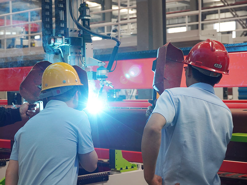
Pipe curvature creates a continuous orientation challenge.
As the torch moves around a circumferential weld, the local surface direction changes constantly.
The robot must therefore maintain the appropriate relationship between:
- electrode or wire
- joint centerline
- pipe surface
- travel direction
If the robot simply follows the geometric center of the seam without adjusting torch orientation, the welding angle may gradually become unsuitable.
This is why robotic pipe welding programs often contain both position and orientation information.
The robot is not only instructed where to move.
It must also know how the torch should be oriented at each point.
For more complex pipe intersections, this orientation may change in several axes simultaneously.
Smooth path generation becomes especially important because abrupt wrist movements can interfere with stable welding motion.
Managing Start and Stop Locations
Pipe welding often involves closed-loop seams.
That means the robot eventually returns to the area where welding began.
The start and stop region deserves careful process planning because it can influence the continuity of the completed weld.
Programming should define:
- exact arc start position
- stabilization movement
- travel direction
- overlap strategy where appropriate
- arc stop behavior
- final torch motion
The goal is to ensure that the transition between the beginning and end of the circumferential weld remains controlled and repeatable.
In multi-pass applications, the challenge becomes greater because subsequent weld paths must remain correctly positioned relative to earlier passes.
This is another area where consistent workpiece positioning and path control become essential.
Robotic Pipe Welding for Multi-Pass Joints
Some pipe joints require more than one weld pass.
In manual welding, an experienced operator can visually assess the previous bead and adjust the next pass.
Robotic multi-pass welding requires that relationship to be translated into controlled paths and process logic.
The system must understand where each pass should be placed relative to the joint and previous weld geometry.
Possible strategies include:
- predefined offset paths
- stored multi-pass programs
- sensor-based seam identification
- adaptive path adjustment
- controlled workpiece rotation
The suitability of each approach depends on joint geometry and the amount of variation expected between components.
Multi-pass robotic pipe welding generally requires stronger process control than single-pass welding because errors in an early pass can influence every later pass.
High-Mix Pipe Fabrication and Robotic Flexibility
Pipe fabrication does not always involve long runs of identical components.
Manufacturers may process several pipe diameters, lengths, intersections, joint angles, or assembly configurations.
This creates a high-mix automation challenge.
Traditional fixed programming can still work, but the number of programs and setup changes can grow quickly.
More flexible robotic pipe welding systems may use:
- parameterized programs
- digital workpiece models
- vision-based part recognition
- automatic seam detection
- reusable welding procedures
- adjustable fixtures
- programmable positioners
The objective is to separate what changes from what remains constant.
For example, a family of pipe assemblies may use different diameters while sharing the same basic joint type and welding procedure.
A flexible system can use those common elements rather than treating every product as an entirely new automation project.
How Robot Reach Affects Pipe Welding Cell Design
Robot reach should not be evaluated only by comparing maximum reach with workpiece dimensions.
A robot operates best within an effective working envelope.
When welding near the extreme edge of its reach, maintaining appropriate torch orientation can become difficult.
Large pipe assemblies may therefore require:
- a linear robot track
- workpiece rotation
- multiple robot positions
- multi-axis positioners
- alternative cell layouts
Collision analysis is equally important.
The robot must avoid the pipe itself, fixture components, positioner structures, welding cables, and surrounding equipment.
Simulation before final installation can help identify these issues before they become physical limitations.
The best cell layout is the one that allows smooth access to all required joints without forcing the robot into repeated extreme configurations.
When Robotic Pipe Welding Makes the Most Sense
Robotic pipe welding provides the strongest value when the process contains repeated or structured welding tasks.
Good candidates often have:
- recurring pipe joints
- controlled component dimensions
- predictable assembly geometry
- stable welding procedures
- repeated production
- accessible seams
- suitable fixture references
- measurable joint variation
Complexity alone does not make robotic welding unsuitable.
A complicated three-dimensional joint can still be automated if its geometry is predictable.
The greater challenge is unpredictability.
A simple-looking joint that changes significantly from component to component may be harder to automate than a complex joint that repeats consistently.
This is why process repeatability is often more important than geometric simplicity.
Common Robotic Pipe Welding Mistakes
One common mistake is assuming that a rotational positioner automatically solves circumferential welding.
The positioner must still locate the pipe accurately and coordinate correctly with the welding process.
Another mistake is ignoring variation in branch intersections.
If pipe cutting and assembly move the real seam away from the programmed geometry, the robot needs either improved process control or a way to identify that change.
Torch access is also frequently underestimated.
Fixtures that hold pipes securely can obstruct the torch or robot wrist.
Manufacturers should also avoid designing the automation around an ideal sample component.
Testing should use representative production workpieces that include normal dimensional and assembly variation.
Finally, the complete process should be examined.
If loading, alignment, tack welding, or positioning remains unstable, automating the final welding operation alone may not solve the underlying manufacturing problem.
How to Evaluate a Robotic Pipe Welding Application
A useful evaluation begins by grouping pipe components according to joint type and geometry.
Identify:
- pipe diameters
- joint configurations
- branch angles
- seam lengths
- expected dimensional tolerances
- welding processes
- required orientations
- access limitations
Then examine the actual production flow.
Determine how pipes are cut, assembled, located, tack welded, transferred, and positioned before final welding.
Measure real variation rather than relying only on drawings.
After that, determine whether fixtures can control the variation or whether sensing should be added.
Robot reach, positioner movement, torch geometry, and collision clearance should then be evaluated together.
This process provides a much stronger foundation than selecting equipment first and attempting to adapt the workpiece afterward.
The Future of Robotic Pipe Welding
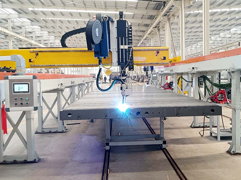
Robotic pipe welding is moving toward systems that require less fixed point teaching and can respond more effectively to actual joint geometry.
Vision, seam sensing, digital models, automatic path generation, and adaptive control are becoming increasingly important for complex pipe structures.
The most important change is the ability to connect digital geometry with real workpiece information.
A digital model may define where the seam should be.
A sensor can determine where the seam actually is.
The robot can then apply a validated welding procedure along a corrected path.
This approach is particularly useful for high-mix fabrication where joint geometry remains structured but component dimensions or positions vary within known limits.
Future systems will still depend on good fixtures, welding engineering, and stable upstream processes.
Automation becomes more intelligent when better information is available, not when basic manufacturing control is ignored.
Conclusion
Robotic pipe welding can handle complex joints effectively when the robot, positioner, fixture, sensing technology, and welding process are designed as one coordinated system.
Circumferential seams can be simplified through controlled workpiece rotation. Branch joints can be managed with three-dimensional path planning. Seam sensing can compensate for predictable variation, while accurate fixtures provide the repeatable reference the robot requires.
The most important factor is not whether a pipe joint looks complicated.
It is whether the geometry, variation, and production process can be understood and controlled.
When those conditions are in place, robotic pipe welding can turn difficult repeated joints into stable, programmable manufacturing operations while retaining the flexibility needed for different pipe assemblies.
FAQ
What is robotic pipe welding?
Robotic pipe welding uses a programmable robot to control welding torch movement around pipe joints such as circumferential seams and branch connections. Systems can also use positioners, fixtures, seam sensing, and coordinated axes to maintain accurate torch position around complex geometry.
Can robotic pipe welding handle different pipe diameters?
Yes. Different diameters can be handled through separate or parameterized programs, adjustable fixtures, sensing, and programmable positioners. The system must still account for changes in curvature, joint location, torch orientation, reach, and expected workpiece variation.
How does a robot weld around a complete pipe?
The robot can move the torch around a stationary pipe, or a positioner can rotate the pipe while the robot maintains a controlled torch orientation. The second approach can simplify some circumferential joints, but the best method depends on workpiece geometry and cell layout.
Is seam tracking necessary for robotic pipe welding?
Not always. Fixed paths work well when pipe location and joint geometry repeat accurately. Seam tracking becomes more useful when normal cutting, assembly, or fixture tolerances shift the real joint position within a predictable range that the robotic system needs to compensate for.
Can robotic pipe welding handle branch connections?
Yes, provided the robot can maintain suitable access and torch orientation along the three-dimensional seam. Branch joints may require more advanced path planning, sensing, fixtures, or coordinated positioning because the welding path changes continuously around the pipe intersection.
Need Help Choosing the Right Robotic Pipe Welding Solution?
If you’re unsure how robotic pipe welding can handle your pipe diameters, joint geometries, branch connections, positioners, fixtures, or seam variation, our team can help evaluate the complete welding process. Contact SHUIPO for a technical consultation and develop an automation approach around your real production conditions.