
جدول المحتويات
مقدمة
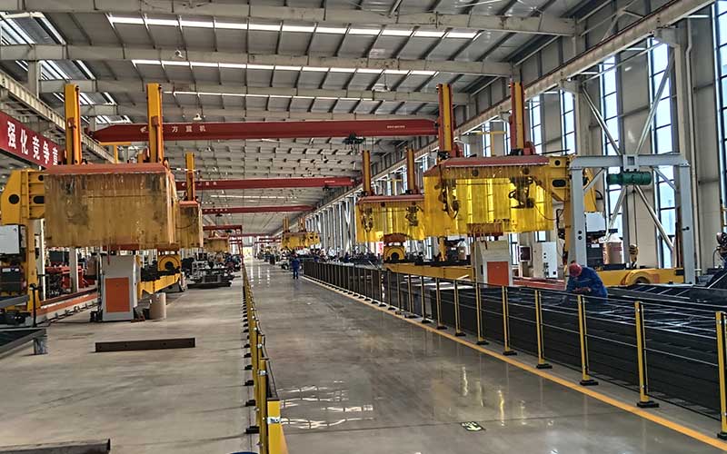
يمكن لمنصة الرفع الهيدروليكي أن تحل واحدة من أكثر المشكلات شيوعًا في التعامل مع المواد الصناعية: تحريك الحمولة بأمان ودقة بين ارتفاعات العمل المختلفة.
في بيئة الإنتاج الآلية، قد تحتاج المواد إلى النقل بين مركبة AGV، أو ناقل، أو رف تخزين، أو تركيبات لحام، أو محطة تجميع، أو طاولة فحص، أو موضع تحميل. عندما لا تكون هذه الواجهات على نفس الارتفاع، يمكن أن يتوقف تدفق المواد حتى لو كانت كل آلة على حدة تعمل بكفاءة.
تعمل منصة الرفع الهيدروليكية المصممة بشكل صحيح على إنشاء اتصال رأسي متحكم فيه بين هذه العمليات. يمكنها رفع المنصات أو التركيبات أو الحاويات أو قطع العمل أو العربات أو حاملات الإنتاج إلى ارتفاع نقل قابل للتكرار مع دعم التحميل والتفريغ المستقر.
ومع ذلك، فإن اختيار منصة تعتمد فقط على سعة الحمولة وارتفاع الرفع نادرًا ما يكون كافيًا. تؤثر أبعاد المنصة، وتوزيع الحمل، والصلابة الهيكلية، والضغط الهيدروليكي، وترتيب الأسطوانة، والتحكم في الشوط، ودقة الإرساء، ودورة العمل، وأجهزة السلامة، واتصالات النظام على الأداء النهائي.
يوضح هذا الدليل:
- كيف تعمل منصة الرفع الهيدروليكية
- تكوينات المنصة الرئيسية المستخدمة في الصناعة
- كيفية تحديد سعة الحمولة المطلوبة
- لماذا يهم توزيع الحمل بقدر الوزن الإجمالي
- كيف يمكن للمصاعد الهيدروليكية أن تعمل مع المركبات AGV والناقلات
- ما هي وظائف السلامة والتحكم التي ينبغي تضمينها
- ما الذي يسبب الرفع غير المستقر وتحديد المواقع غير الدقيق
- كيفية تقييم النظام الأساسي قبل تكامل النظام
ما هي منصة الرفع الهيدروليكية؟
منصة الرفع الهيدروليكية عبارة عن جهاز للتعامل مع الأحمال يستخدم القوة الهيدروليكية لرفع أو خفض المنصة على طول مسار رأسي يتم التحكم فيه.
يمكن تركيب المنصة بشكل دائم بجانب معدات الإنتاج، أو دمجها في ناقل، أو تركيبها على مركبة متنقلة، أو دمجها في نظام آلي للتعامل مع المواد. ويتمثل دورها الرئيسي في تغيير الوضع الرأسي للحمولة دون الحاجة إلى رفع يدوي مستمر.
مبدأ التشغيل يأتي من الهيدروليكية, ، حيث ينقل السائل المضغوط القوة عبر المضخات والصمامات والأنابيب والأسطوانات الهيدروليكية.
تشتمل منصة الرفع الهيدروليكية النموذجية على ما يلي
- منصة دعم التحميل
- واحدة أو أكثر من الأسطوانات الهيدروليكية
- وحدة الطاقة الهيدروليكية
- خزان النفط
- مضخة ومحرك
- صمامات التحكم الاتجاهية
- صمامات التحكم في الضغط
- الخراطيم الهيدروليكية أو الأنابيب الصلبة
- الإطار الهيكلي
- آلية الدليل
- أجهزة استشعار الموقف
- مفاتيح الحد العلوي والسفلي
- أقفال السلامة
- نظام خفض الطوارئ
- تحكم كهربائي
تقوم بعض الأنظمة الأساسية بحركة بسيطة لأعلى ولأسفل فقط. يمكن للإصدارات الأكثر تقدمًا أن تتوقف تلقائيًا عند عدة ارتفاعات، وتتواصل مع معدات الإنتاج، وتكتشف وجود الحمل، وتؤكد اكتمال النقل، وتنسق مع برنامج جدولة AGV.
كيف تعمل منصة الرفع الهيدروليكية؟
تتكون دورة التشغيل الأساسية من التحميل والرفع وتحديد المواقع والنقل والخفض وإعادة الضبط.
كشف الحمل
يتم وضع المادة على المنصة بواسطة مشغل أو رافعة شوكية أو رافعة أو ناقل أو روبوت أو AGV.
قد يؤكد مستشعر التواجد أن الحمل قد وصل إلى الموضع الصحيح. في التطبيقات الآلية، يجب أن تميز وحدة التحكم بين المنصة المشغولة أو المحملة بشكل غير صحيح أو الجاهزة للرفع.
توليد الضغط الهيدروليكي
يقوم المحرك الكهربائي بتشغيل المضخة الهيدروليكية، التي تنقل الزيت من الخزان إلى دائرة الأسطوانة.
عندما يدخل السائل إلى الأسطوانة، يخلق الضغط الهيدروليكي قوة ميكانيكية. يمتد قضيب المكبس أو يتراجع حسب تصميم النظام، مما يتسبب في ارتفاع المنصة أو انخفاضها.
الحركة العمودية الموجهة
يجب أن تتحرك المنصة على طول مسار محدد. تتحكم أذرع المقص أو الأعمدة أو القضبان أو البكرات أو كتل التوجيه أو الروابط الهيكلية في هذه الحركة.
تقاوم الأدلة القوى الجانبية وتساعد على منع المنصة من التحرك أو الدوران أو الإمالة أثناء التشغيل.
تحديد الارتفاع
تخبر مفاتيح الحد أو أجهزة استشعار القرب أو أجهزة التشفير أو أجهزة استشعار الإزاحة وحدة التحكم عندما تصل المنصة إلى المستوى المطلوب.
قد يتوقف النظام الأساسي عند حدوده العليا والدنيا فقط. قد تحتاج منصة خط الإنتاج إلى عدة ارتفاعات نقل مبرمجة.
نقل الحمولة
بمجرد تأكيد الارتفاع الصحيح، يقوم الناقل أو الطاولة الدوارة أو وحدة السلسلة أو الدافع أو AGV أو المشغل بنقل المادة إلى المحطة التالية.
يجب أن تظل المنصة مستقرة أثناء النقل. يمكن أن تؤدي الحركة الرأسية المفرطة أو انحراف المنصة أو عدم تطابق الارتفاع إلى مقاطعة العملية.
خفض متحكم فيه
يسمح صمام التحكم للسائل الهيدروليكي بالعودة إلى الخزان بمعدل منظم.
تمنع دائرة التخفيض التي يتم التحكم فيها المنصة من الانخفاض بسرعة، حتى عندما يكون الحمل ثقيلًا أو يفقد النظام الطاقة.
الأنواع الرئيسية لمنصات الرفع الهيدروليكية
يعتمد الهيكل الصحيح على ارتفاع الرفع والحمل وحجم المنصة ومساحة التثبيت المتاحة وطريقة النقل ومستوى الأتمتة المطلوب.
منصة رفع المقص
يستخدم المصعد المقص أذرعًا هيكلية متقاطعة تفتح وتغلق أثناء تحرك الأسطوانة الهيدروليكية.
إنها واحدة من التكوينات الأكثر شيوعًا للتعامل الرأسي مع المواد لأنها توفر مساحة كبيرة للمنصة ويمكن أن تظل مدمجة عند خفضها بالكامل.
تشمل التطبيقات النموذجية ما يلي:
- تحديد المواقع البليت
- تعديل ارتفاع الناقل
- محطات عمل التجميع
- محطات التحميل
- نقل خط الإنتاج
- رفع التركيبات
- التدريج المادي
يجب تقييم آلية المقص للتأكد من ثبات المنصة عند الحد الأدنى والحد الأقصى للارتفاع. يجب أن يظل الحمل ضمن نطاق مركز الجاذبية المصمم.
منصة ذات مقص واحد
يستخدم التصميم ذو المقص الواحد مجموعة رئيسية واحدة من الأذرع المتقاطعة.
إنها مناسبة عندما تكون شوط الرفع المطلوب معتدلاً ويمكن لمنطقة التثبيت استيعاب الآلية.
النظام واضح ومباشر نسبيًا، لكن طول المنصة وموضع التحميل لا يزالان يؤثران على إجهاد الذراع والانحراف الهيكلي.
منصة مزدوجة أو متعددة المقص
يمكن ترتيب أقسام مقصية متعددة عموديًا لإنشاء ارتفاع رفع أكبر.
يوفر هذا التكوين شوطًا طويلًا داخل منطقة قاعدة محدودة. ومع ذلك، يمكن أن يؤدي الارتفاع الأكبر إلى زيادة الحساسية للأحمال الجانبية، والتحميل غير المتساوي، وتآكل الدليل، وحركة المنصة.
قد تتطلب الأنظمة الطويلة استقرارًا إضافيًا وتحليلًا هيكليًا أكثر تفصيلاً.
منصة رفع منخفضة المستوى
تم تصميم منصة منخفضة المستوى بارتفاع مغلق منخفض.
يكون مفيدًا عندما يجب وضع الحمولة بالقرب من مستوى الأرضية أو عندما لا تتوفر حفرة تركيب عميقة.
قد يتطلب هيكلها المدمج ترتيبًا متخصصًا للمقص أو موضع الأسطوانة أو إطار المنصة.
منصة مثبتة على الحفرة
يتم تركيب مصعد مثبت على الحفرة أسفل مستوى الأرضية المحيطة بحيث يمكن أن تصبح المنصة متسقة مع الأرضية عند خفضها بالكامل.
يسمح هذا التصميم للمنصات والعربات والناقلات ذات العجلات بالانتقال إلى المنصة بدون منحدر.
يجب أن يأخذ التثبيت في الاعتبار الصرف والتنظيف والوصول إلى الصيانة والدعم الهيكلي والحماية حول فتحة الحفرة.
منصة رفع موجهة بالعمود
يستخدم رفع العمود الصواري الرأسية أو السلاسل أو الأسطوانات أو بكرات التوجيه أو عربات الرفع لتحريك المنصة.
يمكن أن يوفر حركة رأسية يمكن التحكم فيها مع مساحة أرضية صغيرة نسبيًا. قد تكون مناسبة لنقل الأحمال بين مستويات الإنتاج أو المحطات المرتفعة.
يجب أن تظل أعمدة التوجيه محاذية وصلبة تحت الحمل المتوقع.
منصة رفع هيدروليكية متنقلة
تجمع المنصة المتنقلة بين القدرة على الرفع والعجلات أو الهيكل الذي يعمل بالطاقة أو مركبة النقل الآلية.
يمكنه جمع حمولة على ارتفاع واحد، ونقلها إلى موقع آخر، ورفعها أو خفضها للنقل.
يتطلب الرفع المتحرك اهتمامًا إضافيًا بثبات السيارة ومركز الثقل وحالة الأرضية والفرملة والأقفال المتشابكة التي تمنع السفر في وضع غير آمن للمنصة.
منصة رفع هيدروليكية مثبتة على AGV
تسمح المنصة المثبتة على AGV للمركبة الآلية برفع منصة نقالة أو تركيبات أو رف أو حامل مباشرة.
قد ترتفع المنصة مسافة قصيرة فقط لتجميع الحمل من منصات الدعم، أو قد توفر شوطًا أكبر لرسو محطة العمل.
آن مركبة خدمة AGV مجهزة بآلية تحميل مناسبة يمكنها ربط المناولة الرأسية بالنقل الأفقي الآلي. يجب تصميم السيارة والمنصة وهيكل الإرساء وأجهزة الاستشعار وأدوات التحكم في الإنتاج كنظام واحد كامل.
مقارنة منصة الرفع الهيدروليكية
| نوع المنصة | التطبيق الأنسب | الميزة الرئيسية | القيد الرئيسي | نقطة التقييم الرئيسية |
|---|---|---|---|---|
| رفع بمقص واحد | محطة العمل العامة ورفع الناقل | منصة مستقرة ذات هيكل بسيط | ارتفاع رفع معتدل | موضع التحميل وانحراف المنصة |
| رفع متعدد المقص | سفر عمودي أكبر | ضربة طويلة من قاعدة مدمجة | أكثر حساسية للتحميل الجانبي | دليل الاستقرار في أقصى ارتفاع |
| رفع منخفض المستوى | تحميل على مستوى الأرض | ارتفاع مغلق صغير | آلية أكثر تخصصا | التخليص تحت المنصة |
| مصعد مثبت على الحفرة | نقل أرضية متدفقة | سهولة الوصول إلى العربة والمنصة | يتطلب التثبيت المدني | حماية الحفرة والصرف |
| رفع موجه بالعمود | نقل عمودي متعدد المستويات | بصمة قاعدة صغيرة | يتطلب أدلة رأسية صلبة | محاذاة العمود |
| منصة رفع متنقلة | تحديد موضع المواد المرنة | يمكن أن يتحرك الرفع بين المحطات | تغيرات الاستقرار أثناء السفر | مركز الثقل |
| مصعد مثبت على AGV | الاستلام والتسليم الآلي | يجمع بين الرفع والنقل | يتطلب إرساء دقيق | تكامل منصة السيارة |
كيفية تحديد سعة التحميل المطلوبة
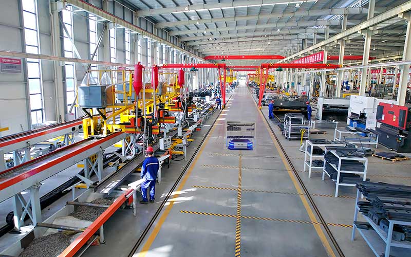
لا ينبغي تحديد سعة الحمولة فقط من خلال قراءة الوزن الاسمي للمنتج الذي يتم رفعه.
يجب أن تدعم المنصة حمل الرفع الكامل، بما في ذلك:
- قطعة العمل
- منصة نقالة
- تركيبات
- حاوية
- إطار النقل
- وحدة الناقل
- الكابلات أو الخراطيم التي تحملها المنصة
- مرفقات الإنتاج المؤقتة
- اختلاف التحميل المحتمل
يجب تحديد الحد الأقصى لحمل التشغيل المتوقع من ظروف الإنتاج الحقيقية وليس من المنتج المتوسط.
حمل ثابت
الحمل الثابت هو الوزن الذي يستقر على المنصة عندما لا تتحرك.
هذه القيمة مهمة، لكنها لا تمثل المتطلبات الهيكلية بأكملها.
الحمل الديناميكي
يؤدي التسارع والتباطؤ والبدء والتوقف ونقل الأحمال إلى إنشاء قوى إضافية.
قد ينتج عن الحمل الذي يتم وضعه فجأة بواسطة رافعة شوكية أو نقله من ناقل متحرك قوة مؤقتة أكبر من وزنه الثابت.
حمل غريب الأطوار
يتم وضع الحمل اللامركزي بعيدًا عن مركز المنصة.
يؤدي هذا إلى إنشاء قوى غير متساوية على الإطار وأذرع المقص والأدلة والدبابيس والأسطوانات والقاعدة. يمكن لحملين لهما نفس الوزن الإجمالي أن يخلقا ظروفًا هيكلية مختلفة جدًا اعتمادًا على مواقعهما.
الحمل المركز
يطبق الحمل المركز الوزن من خلال منطقة اتصال صغيرة، مثل أقدام البليت الضيقة أو دعامات الماكينة أو عجلات العربة.
قد يحتاج سطح المنصة إلى تعزيز محلي حتى عندما يظل الحمل الإجمالي ضمن السعة المقدرة.
الحمل المتداول
عندما تتحرك عربة أو شاحنة نقالة أو حاملة ذات عجلات عبر المنصة، ينتقل وزنها من حافة إلى أخرى.
يجب أن يدعم الهيكل تغيير مواضع التحميل أثناء الدخول والخروج، وليس فقط موضع التوقف النهائي.
لماذا يهم توزيع التحميل
يفترض تصنيف المنصة عادةً ظروف تحميل محددة. يمكن أن يؤدي وضع الحمولة الكاملة بالقرب من حافة واحدة إلى إنتاج ضغط أعلى من وضعها بالتساوي عبر السطح.
التحميل غير المتساوي يمكن أن يسبب:
- إمالة المنصة
- ارتداء الدليل
- تحميل الاسطوانة غير متساو
- تشويه ذراع المقص
- ارتداء دبوس وجلبة
- انحراف الإطار
- أخطاء تحديد الارتفاع
- الاتصال بين المكونات المتحركة
- انخفاض استقرار التشغيل
يجب تحديد مركز التحميل في جميع الأبعاد الثلاثة.
مركز الثقل الأفقي
يجب أن يظل الحمل داخل منطقة المنصة المقصودة. قد تمتد المنتجات الطويلة إلى ما وراء السطح وتحول مركز الجاذبية المشترك.
مركز الثقل العمودي
يخلق الحمل الطويل تأثيرًا انقلابيًا أكبر من الحمل المنخفض الذي له نفس الوزن.
يصبح هذا مهمًا بشكل خاص على المنصات المتنقلة وعلى أقصى ارتفاع للرفع.
تغيير مركز الثقل
قد تتغير السوائل والأجزاء المعلقة والتركيبات المتحركة والمكونات المدعومة بشكل غير محكم أثناء تحرك المنصة.
لا ينبغي للنظام أن يفترض أن مركز الثقل يظل ثابتًا ما لم يتم تأمين الحمل بشكل صحيح.
اتجاه نقل الحمولة
يمكن للناقل الذي ينقل المواد بشكل جانبي أن يخلق قوى مختلفة عن العربة التي تدخل من الأمام.
ينبغي تقييم الهيكل والأدلة في اتجاه النقل الفعلي.
حجم المنصة والصلابة الهيكلية
يجب أن تكون المنصة كبيرة بما يكفي لدعم الحمل ولكن لا ينبغي توسيعها دون النظر إلى العواقب الهيكلية.
يزيد السطح الأوسع أو الأطول من المسافة بين الحمل والآلية الداعمة. وهذا يمكن أن يزيد من إجهاد الانحناء والانحراف.
طول المنصة
تعتبر المنصات الطويلة مفيدة للمكونات كبيرة الحجم، ولكنها قد تنحرف بالقرب من الأطراف عندما لا يكون الحمل في المنتصف.
يجب أن يتطابق هيكل الدعم مع مواقع التحميل المتوقعة.
عرض المنصة
يجب أن يسمح العرض بالتحميل الآمن مع التحكم في الحركة الجانبية.
قد يتطلب العرض المفرط أعضاء متقاطعة أقوى، أو تباعدًا أكبر بين الدليل، أو ترتيبًا مختلفًا للأسطوانة.
سطح السفينة
قد يستخدم سطح المنصة:
- لوحة مسطحة
- لوحة مضادة للانزلاق
- بكرات
- سلاسل
- سيور ناقلة
- تحديد المواقع دبابيس
- فتحات تركيب التركيبات
- قضبان التوجيه
- تتوقف العجلة
يجب أن يدعم تصميم السطح طريقة النقل ويمنع حركة الحمل غير المقصودة.
الانحراف الهيكلي
يمكن أن تظل المنصة أقل من حد قوة المواد الخاص بها وتظل منحرفة بدرجة كافية للتسبب في مشكلة النقل.
على سبيل المثال، قد تتوقف منصة الناقل عند موضع المستشعر الصحيح بينما تقع حافتها المحملة أسفل ناقل الاستقبال. يمكن أن يؤدي فرق الارتفاع الناتج إلى سد منصة نقالة أو إحداث تأثير أثناء النقل.
ولذلك فإن الصلابة الوظيفية لا تقل أهمية عن القوة الهيكلية الأساسية.
ارتفاع الرفع والسكتة الدماغية والارتفاع المغلق
وينبغي تحديد ثلاثة أبعاد بشكل منفصل.
الحد الأدنى لارتفاع المنصة
يحدد الحد الأدنى للارتفاع ما إذا كان يمكن للحمل الدخول من مستوى الأرضية، أو ناقل منخفض، أو AGV، أو محطة عمل.
إذا كان الحد الأدنى المنخفض للارتفاع ضروريًا، فقد يحتاج النظام إلى حفرة أو آلية متخصصة منخفضة المستوى.
الحد الأقصى لارتفاع المنصة
يجب أن يتطابق الحد الأقصى للارتفاع مع أعلى نقطة نقل مطلوبة مع ترك ما يكفي من التسامح مع التعديل.
لا ينبغي أن تعتمد المنصة على التشغيل مقابل موضعها النهائي الميكانيكي لتحقيق محاذاة النقل العادية.
رفع السكتة الدماغية
السكتة الدماغية هي المسافة العمودية بين الحد الأدنى والحد الأقصى للمواضع.
يؤدي الشوط الأكبر إلى تغيير متطلبات الأسطوانة وهندسة المقص وطول الدليل والحجم الهيدروليكي ووقت الرفع والاستقرار الهيكلي.
مستويات النقل
تحتاج بعض الأنظمة إلى ارتفاعين فقط. ويجب أن يتوقف البعض الآخر عند عدة محطات.
يجب برمجة كل مستوى نقل واستشعاره ودعمه ميكانيكيًا بدقة كافية لمعدات الاستقبال.
تصميم النظام الهيدروليكي
تحدد الدائرة الهيدروليكية كيفية توليد المنصة للقوة، والتحكم في السرعة، والحفاظ على موضعها، والاستجابة للأخطاء.
وحدة الطاقة الهيدروليكية
تشتمل وحدة الطاقة عادةً على المحرك والمضخة والخزان والمرشحات والصمامات ومكونات التحكم.
يجب أن يوفر تدفقًا كافيًا للسوائل لسرعة الرفع المطلوبة وضغطًا كافيًا للحمل الأقصى.
ترتيب الاسطوانة
قد تستخدم المنصة أسطوانة واحدة، أو أسطوانتين متزامنتين، أو عدة مشغلات رفع.
يمكن للأسطوانات المتعددة تحسين توزيع القوة، ولكنها تتطلب أيضًا طريقة للحفاظ على الحركة المتزامنة.
التحكم بالضغط
يحد صمام التنفيس من الضغط الزائد للنظام.
تعتبر الحماية من الضغط مهمة، ولكن لا ينبغي استخدامها كوسيلة عادية لتحديد ما إذا كان الحمل مقبولاً أم لا. يجب أن يمنع نظام التحكم التحميل الزائد الروتيني قبل الوصول إلى حد الضغط.
التحكم في التدفق
تنظم صمامات التحكم في التدفق سرعة الرفع والخفض.
تعتبر الحركة المستقرة ذات أهمية خاصة بالقرب من مستويات النقل، حيث يمكن أن تؤثر الحركة المفاجئة على المحاذاة.
صمام حمل
تساعد وظيفة حمل الحمولة أو الموازنة على منع الخفض غير المنضبط في حالة فشل الخرطوم أو مكون الدائرة.
يجب أن يتوافق الترتيب الدقيق للصمام مع اتجاه الأسطوانة وتصميم المنصة.
حالة الزيت الهيدروليكي
يمكن أن يؤدي الزيت الملوث إلى إتلاف المضخات والصمامات والأختام والأسطوانات.
تؤثر إجراءات الترشيح ونظافة الخزان وإدارة درجة الحرارة والصيانة بشكل مباشر على الموثوقية على المدى الطويل.
دقة تحديد المواقع والتحكم في الارتفاع
قد تحتاج المنصة الهيدروليكية إلى أكثر من مجرد الرفع الأساسي. غالبًا ما يتطلب النقل الآلي دقة إيقاف متسقة.
مفاتيح الحد
توفر مفاتيح الحد تأكيدًا بسيطًا للمواضع العلوية والسفلية.
إنها مناسبة للأنظمة التي تعمل فقط بين مستويين ثابتين.
مجسات القرب
يمكن لأجهزة الاستشعار غير المتصلة اكتشاف موضع المنصة أو الأهداف الميكانيكية.
إنها تقلل من الاتصال الجسدي ولكنها لا تزال تتطلب التركيب والحماية الصحيحين.
مستشعر الموضع الخطي
يمكن لمستشعر الإزاحة قياس موضع المنصة أو الأسطوانة بشكل مستمر.
يتيح ذلك لوحدة التحكم إدارة ارتفاعات متعددة ومراقبة ما إذا كانت المنصة تتحرك كما هو متوقع.
توقفات ميكانيكية
يمكن للتوقفات الميكانيكية إنشاء ارتفاع نقل قابل للتكرار وتقليل الاعتماد على الضغط الهيدروليكي وحده.
يجب عليهم المشاركة دون خلق تأثير أو حركة غير مستقرة.
تحديد المواقع في حلقة مغلقة
تقوم الأنظمة الأكثر تقدمًا بمقارنة الموضع المطلوب مع تعليقات المستشعر في الوقت الفعلي.
يمكن لوحدة التحكم إبطاء النظام الأساسي بالقرب من الهدف والتوقف ضمن تسامح محدد.
تباين الارتفاع المرتبط بالحمل
يمكن أن يؤدي الضغط الهيدروليكي والانحراف الهيكلي ودرجة حرارة الزيت والخلوص الميكانيكي إلى اختلاف ارتفاع التحميل عن ارتفاع التفريغ.
ولذلك ينبغي التحقق من صحة محاذاة النقل تحت الأحمال التمثيلية.
دمج منصة الرفع الهيدروليكية مع المركبات AGV
يمكن للمركبات AGV والمنصات الهيدروليكية العمل معًا بعدة طرق.
مصعد ثابت يستقبل حمولة AGV
يقوم AGV بتسليم منصة نقالة أو حامل على مصعد ثابت. تقوم المنصة بعد ذلك برفع الحمولة إلى الناقل أو محطة التجميع أو مستوى التخزين.
يفصل هذا الترتيب النقل الأفقي عن الحركة الرأسية.
جمع AGV من منصة ثابتة
تعمل المنصة الهيدروليكية على خفض المادة إلى ارتفاع نقل AGV. بمجرد تأكيد الالتحام ومحاذاة الارتفاع، يتحرك الحمل إلى السيارة.
يتم تثبيت المصعد مباشرة على AGV
تنتقل السيارة أسفل منصة نقالة أو حامل وترفع منصتها لتجميع الحمولة.
تقلل هذه الطريقة من الحاجة إلى معدات نقل تعمل بالطاقة في كل محطة ولكنها تتطلب هندسة متسقة لحامل الدعم.
إرساء محطة العمل المنسقة
يصل AGV إلى محطة العمل، ويؤكد موقعه، وينشط المصعد، وينقل الحمولة، ويخفض المنصة، ويحصل على إذن بالمغادرة.
يجب التحكم في كل مرحلة من خلال شروط مؤكدة بدلاً من التوقيت وحده.
فهم مفصل ل موثوقية المركبات الموجهة ذاتية القيادة يعد أمرًا مهمًا لأن التعامل مع الأحمال والملاحة والإرساء واستشعار السلامة والشحن وجدولة المهام تؤثر على أداء نظام الرفع الكامل.
متطلبات الإرساء والنقل
لا يمكن لمنصة الرفع الهيدروليكية التعويض عن خطأ الإرساء غير المحدود.
يجب أن تصل السيارة أو الناقل أو العربة ضمن التسامح الموضعي المصمم.
المحاذاة الأفقية
يجب أن يظل مسار التحميل متمركزًا بين جهاز الإرسال والاستقبال.
قد يؤدي اختلال المحاذاة الجانبية إلى تلامس المنصات أو العجلات أو البكرات أو التركيبات مع الأدلة.
المحاذاة العمودية
يجب أن تتوقف المنصة عند ارتفاع يسمح بالنقل السلس.
حتى اختلاف المستوى البسيط يمكن أن يصبح مهمًا عند تحريك منصة نقالة صلبة أو حامل ذو عجلات ثقيلة.
المحاذاة الزاوية
قد يؤدي وصول AGV إلى زاوية إلى إنشاء ربط أثناء النقل.
يمكن للأدلة الميكانيكية تصحيح الأخطاء المحدودة، ولكن يجب معالجة التباين الزاوي الكبير من خلال التحكم في الملاحة والإرساء.
فجوة النقل
يجب أن تكون المساحة الأفقية بين المنصات صغيرة بما يكفي لعبور الحمولة ولكنها كبيرة بما يكفي لمنع اصطدام المعدات.
قد تكون هناك حاجة إلى لوحات جسر أو بكرات أو واجهات موجهة.
تأكيد التحميل
يجب أن تؤكد المستشعرات أن الحمل قد دخل المنصة بالكامل أو غادرها قبل بدء الحركة العمودية.
يمكن أن يؤدي الحمل المنقول جزئيًا إلى تحميل غريب الأطوار شديد.
وظائف السلامة
تقوم منصة الرفع الهيدروليكية بتخزين ونقل طاقة ميكانيكية كبيرة. يجب أن تكون السلامة مدمجة في المعدات وتسلسل التشغيل.
حماية الزائد
يجب أن يمنع النظام التشغيل عندما يتجاوز الحمل الحالة المصممة.
قد يدعم استشعار الضغط اكتشاف الحمل الزائد، ولكن يجب أيضًا مراعاة وضع الحمل والقوى الديناميكية.
حماية من فشل الخرطوم
لا ينبغي أن يؤدي الفقدان المفاجئ للضغط الهيدروليكي إلى الهبوط غير المنضبط.
يمكن لصمامات حمل الحمولة وأجهزة السلامة الميكانيكية أن تحد من هذا الخطر.
دعم الصيانة الميكانيكية
يحتاج موظفو الصيانة إلى دعم ميكانيكي أو جهاز قفل يمنع المنصة من الانخفاض أثناء تنفيذ العمل تحتها.
لا ينبغي التعامل مع الضغط الهيدروليكي وحده كدعم للصيانة.
حراسة نقطة قرصة
تعمل أذرع المقص وقضبان التوجيه والأسطوانات والسلاسل وحواف المنصة على إنشاء مناطق قرصة وقص متحركة.
قد تكون هناك حاجة إلى واقيات ثابتة أو حواجز مرنة أو حواف أمان أو وصول مقيد.
حماية المحيط
عندما تتحرك المنصة فوق مستوى الأرضية، قد يحتاج التثبيت إلى حواجز حماية أو بوابات أو حواجز أو أدوات تحكم في الوصول المتشابكة.
توقف طارئ
يجب أن توقف أجهزة إيقاف الطوارئ الحركة بالطاقة وتضع النظام في حالة خاضعة للرقابة.
يجب أن تمنع عملية الاسترداد إعادة التشغيل غير المتوقعة.
خفض الطوارئ الخاضعة للرقابة
قد تحتاج المنصة إلى طريقة يدوية أو تعمل بالطاقة لخفضها بأمان بعد انقطاع التيار الكهربائي.
يجب أن يظل معدل التخفيض تحت الحمل.
نقل التشابكات
يجب أن تتحرك المنصة فقط بعد وضع الحمولة بالكامل وأن تكون جميع المعدات المتصلة جاهزة.
وبالمثل، لا ينبغي للناقل أو AGV أن يبدأ النقل حتى تصل المنصة وتؤكد الارتفاع الصحيح.
منصة الرفع الهيدروليكية مقابل طرق الرفع الأخرى
المنصة الهيدروليكية ليست الطريقة الوحيدة لتغيير ارتفاع المادة.
| عامل التقييم | منصة الرفع الهيدروليكية | رفع المسمار | رفع سلسلة | رفع هوائي |
| قدرة تحميل عالية | قوي | قوي مع التصميم الصحيح | قوي | عموما أكثر محدودية |
| رفع سلس | جيد مع التحكم في التدفق | دقيقة ولكن قد تكون أبطأ | يعتمد على نظام القيادة | يمكن أن تكون أقل استقرارًا تحت الأحمال المتغيرة |
| نقل الطاقة المدمجة | جيد | يتطلب مكونات محرك ميكانيكية | يتطلب سلاسل وعجلات مسننة | يتطلب إمدادات الهواء المضغوط |
| عقد الموقف | يتطلب ضوابط هيدروليكية وميكانيكية | تحديد المواقع الميكانيكية القوية | مطلوب نظام الفرامل أو الإمساك | يمكن أن تختلف مع ضغط الهواء |
| تركيز الصيانة | الزيت، الأختام، الصمامات، الأسطوانات | البراغي والمحامل والتشحيم | السلاسل، العجلة المسننة، التوتر | جودة الهواء والأختام والصمامات |
| الاستخدام الأنسب | رفع المواد الصناعية الثقيلة | تحديد المواقع بدقة يمكن التحكم فيها | نقل عمودي متعدد المستويات | مهام رفع قصيرة وأخف وزنا |
غالبًا ما يتم اختيار الأنظمة الهيدروليكية للأحمال الثقيلة وتوليد القوة بسلاسة. قد توفر الأنظمة الميكانيكية مزايا عندما يكون تحديد المواقع الثابتة القابلة للتكرار بدرجة كبيرة أو السفر العمودي الطويل هو المطلب الرئيسي.
يجب أن يتطابق الاختيار مع المهمة بدلاً من افتراض أن تقنية واحدة متفوقة في كل تطبيق.
مشاكل منصة الرفع الهيدروليكية الشائعة
المنصة ترتفع بشكل غير متساو
تشمل الأسباب المحتملة التحميل غير المتساوي، أو الأدلة البالية، أو الهواء في الدائرة الهيدروليكية، أو مشاكل تزامن الأسطوانة، أو التشوه الهيكلي، أو الارتباط الميكانيكي.
يجب فحص النظام قبل ضبط الضغط أو التدفق.
يتوقف المصعد تحت الارتفاع المطلوب
قد ينجم ذلك عن عدم كفاية الضغط، أو زيادة التحميل على المنصة، أو تسرب الأسطوانة الداخلية، أو سوء ضبط المستشعر، أو تآكل المضخة، أو الانحراف الهيكلي.
وينبغي مقارنة الارتفاع المحمل والتفريغ.
المنصة تنجرف إلى الأسفل
قد يسمح تسرب الصمام الداخلي أو تسرب ختم الأسطوانة أو إعدادات صمام حمل الحمل غير الصحيحة أو التلوث الهيدروليكي بالحركة التدريجية.
لا ينبغي للمنصة أن تعتمد فقط على المضخة للحفاظ على موضعها.
الحركة متشنجة
الهواء الموجود في النظام، أو الصمامات الملوثة، أو سوء محاذاة الأسطوانة، أو الاحتكاك الميكانيكي، أو التدفق غير المستقر، أو دائرة خفض غير مناسبة يمكن أن يسبب حركة غير منتظمة.
يؤدي الرجيج المتكرر إلى زيادة تآكل المكونات ويمكن أن يزعزع استقرار الحمل.
ارتفاع درجة حرارة الزيت الهيدروليكي
تشمل الأسباب المحتملة تخفيف الضغط المستمر، أو خزان صغير الحجم، أو التدوير المفرط، أو التدفق المحدود، أو التسرب الداخلي، أو لزوجة الزيت غير الصحيحة، أو التبريد غير الكافي.
تغير الحرارة أداء الزيت ويمكن أن تقصر عمر الختم.
تكون المنصة مستوية عندما تكون فارغة ولكنها تميل عند التحميل
قد يكون الحمل خارج المركز المقصود، أو قد يفتقر هيكل المنصة إلى الصلابة، أو قد يكون للموجهات خلوص مفرط، أو قد تكون قوى الأسطوانة غير متساوية.
يجب أن يستخدم الاختبار الحمل الحقيقي واتجاه النقل.
لا يمكن لـ AGV إكمال نقل الحمولة
تشمل الأسباب المحتملة خطأ الإرساء، أو عدم تطابق الارتفاع، أو شوط الرفع غير المكتمل، أو انحراف المنصة، أو عدم موافقة المستشعر، أو فجوة النقل المفرطة، أو اختلال التحميل.
يجب تشخيص AGV ومنصة الرفع كنظام واحد متصل.
متطلبات الصيانة
تساعد الصيانة الوقائية في الحفاظ على دقة الرفع وتقليل الانقطاعات غير المخطط لها.
زيت هيدروليكي
التحقق من مستوى الزيت والمظهر ودرجة الحرارة والتلوث.
يجب أن يتبع استبدال الزيت حالة التشغيل الفعلية وخطة صيانة المعدات.
المرشحات
يمكن للمرشحات المحظورة تقييد التدفق وزيادة فقدان الضغط.
يجب مراقبة حالة الفلتر بدلاً من انتظار حدوث عطل هيدروليكي واضح.
الاسطوانات والأختام
افحص قضبان الأسطوانة بحثًا عن التسجيل أو التلوث أو التآكل أو التسرب.
يمكن لأسطح القضبان التالفة أن تتآكل الأختام بسرعة.
الخراطيم والتجهيزات
ابحث عن التآكل والتشقق والتسرب والتجهيزات السائبة والاتصال بالهياكل المتحركة.
يجب توجيه الخراطيم بعيدًا عن نقاط الضغط والحواف الحادة.
دبابيس وبطانات
تواجه محاور المقص والمفاصل الهيكلية حركة متكررة تحت الحمل.
يمكن أن يؤدي التآكل إلى زيادة خلوص المنصة وتقليل استقرار تحديد المواقع.
مكونات الدليل
يجب أن تظل بكرات التوجيه والشرائح والأعمدة والقضبان محاذية ومعدلة بشكل صحيح.
قد يكون ارتداء الدليل غير المتساوي علامة على التحميل خارج المركز.
أجهزة الاستشعار
يجب اختبار أجهزة استشعار الموضع والحمل والبوابة والنقل في ظل ظروف التشغيل الحقيقية.
قد يظل المستشعر الذي يعمل أثناء الفحص اليدوي يفشل تحت الاهتزاز أو التلوث.
الاتصالات الهيكلية
افحص اللحامات والمسامير ونقاط التثبيت ودعامات المنصة وإطارات التثبيت.
يجب فحص التشوه المرئي أو المثبتات السائبة المتكررة بدلاً من تشديدها بشكل متكرر.
كيفية اختيار منصة الرفع الهيدروليكية
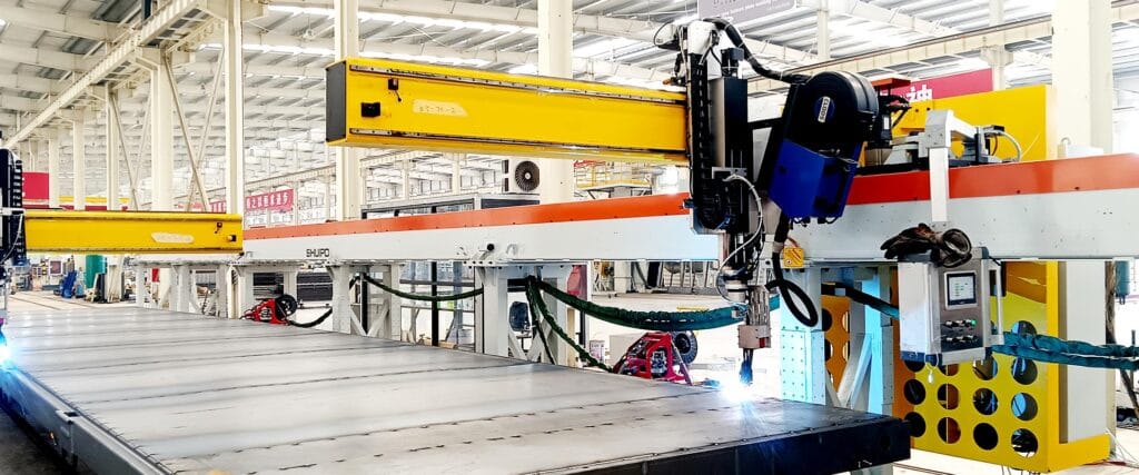
تساعد عملية الاختيار المنظمة على ضمان تطابق المنصة مع مهمة الإنتاج الكاملة.
الخطوة 1: تحديد الحمل
سجل الحد الأقصى لوزن المنتج، والمنصة، والتركيب، والحامل، وأبعاد الحمولة، ومركز الثقل، والتنوع المحتمل.
الخطوة 2: تحديد كل ارتفاع نقل
قم بقياس أدنى نقطة تحميل وأعلى نقطة تسليم ومستويات متوسطة وتحمل الارتفاع المسموح به.
الخطوة 3: تأكيد طريقة النقل
تحديد ما إذا كانت المواد تدخل عن طريق الرافعة الشوكية أو العربة أو الناقل أو AGV أو الروبوت أو الرافعة أو التحميل اليدوي.
تؤثر طريقة النقل على تصميم السطح وصلابة المنصة ومتطلبات المستشعر.
الخطوة 4: مراجعة تردد التشغيل
سجل الدورات المتوقعة في الساعة، وساعات التشغيل، ومسافة الرفع، والسفر المحمل، ووقت الانتظار.
يجب أن تتطابق الوحدة والهيكل الهيدروليكي مع دورة العمل الحقيقية.
الخطوة 5: تقييم مساحة التثبيت
قياس مساحة الأرضية، وتوافر الحفرة، والخلوص العلوي، والوصول إلى الصيانة، والآلات المحيطة، وطرق المشاة، والوصول في حالات الطوارئ.
الخطوة 6: تحليل توزيع الأحمال
تحقق من الأحمال المركزية والغريبة الأطوار والمركزة والمتدحرجة والمتغيرة.
ينبغي تضمين الحالة الواقعية الأكثر خطورة في مراجعة التصميم.
الخطوة 7: تحديد دقة تحديد المواقع
حدد مدى دقة توقف المنصة للعمل اليدوي أو نقل الناقل أو التحميل الآلي أو إرساء AGV.
الخطوة 8: تصميم تسلسل التحكم
قم بإدراج كل التأكيد المطلوب، بما في ذلك وجود الحمولة، وموقع المنصة، وحالة البوابة، والإرساء، وإكمال النقل، وجاهزية المعدات.
الخطوة 9: خطة استرداد الأخطاء
حدد كيفية خفض الحمل أو إزالته أو دعمه أو نقله بعد حدوث خطأ في الطاقة أو المستشعر أو الهيدروليكي أو الاتصال.
الخطوة 10: التحقق من صحة الإنتاج التمثيلي
يجب أن يشمل الاختبار ما يلي:
- الحد الأدنى والحد الأقصى للأحمال
- الأحمال خارج المركز
- ركوب الدراجات المتكررة
- أقصى ارتفاع للرفع
- توقف طارئ
- خفض فقدان الطاقة
- النقل على كل مستوى عمل
- اختلاف إرساء AGV
- أخطاء الاستشعار
- الوصول إلى الصيانة
- انحراف هيكلي محمل
يجب أن يوضح الاختبار النهائي عملية إنتاج موثوقة، وليس فقط أن المنصة يمكنها التحرك لأعلى ولأسفل.
خاتمة
يمكن لمنصة الرفع الهيدروليكي تحسين تدفق المواد الصناعية من خلال توصيل محطات العمل والناقلات والمركبات الزراعية والتركيبات ومواقع التخزين الموجودة على ارتفاعات مختلفة.
يعتمد أدائها على أكثر بكثير من سعة الحمولة الاسمية. توزيع الحمل، ومركز الثقل، وصلابة المنصة، وشوط الرفع، وتصميم الدوائر الهيدروليكية، واستقرار الدليل، ودقة تحديد المواقع، وتحمل الإرساء، وضوابط السلامة، والصيانة، كلها تؤثر على الموثوقية.
تعتبر المصاعد المقصية مناسبة للعديد من مهام الرفع العامة، في حين أن الأنظمة منخفضة المستوى والمثبتة في الحفرة والموجهة بالأعمدة والمتنقلة والمثبتة على AGV تلبي متطلبات أكثر تحديدًا للتعامل مع المواد.
تبدأ أقوى المشاريع بتحليل مفصل لعملية التحميل والنقل. عندما يتم تصميم منصة الرفع الهيدروليكي مع المعدات المحيطة وتسلسل التحكم، فإنها يمكن أن توفر حركة رأسية مستقرة وتدعم سير عمل آلي أكثر استمرارية.
الأسئلة الشائعة
ما هي منصة الرفع الهيدروليكية المستخدمة؟
تعمل منصة الرفع الهيدروليكية على رفع أو خفض المنصات أو التركيبات أو العربات أو قطع العمل أو الحاويات أو ناقلات الإنتاج بين ارتفاعات التشغيل المختلفة. يمكنه توصيل الناقلات ومحطات التجميع ومواقع التخزين والمركبات AGV وغيرها من معدات مناولة المواد في سير العمل اليدوي أو الآلي.
كيف يمكنني اختيار سعة الحمولة لمنصة الرفع الهيدروليكية؟
قم بتضمين المنتج، والمنصة، والتركيبات، ومعدات النقل، والناقل، والملحقات المؤقتة. ضع في اعتبارك أيضًا الأحمال اللامركزية والمركزة والمتدحرجة والديناميكية. يجب تقييم المنصة باستخدام حالة التشغيل الواقعية الأكثر تطلبًا بدلاً من متوسط وزن المنتج.
هل يمكن لمنصة الرفع الهيدروليكي أن تعمل مع AGV؟
نعم. يمكن للرفع الثابت استقبال الأحمال من مركبة AGV، أو يمكن تركيب المصعد مباشرة على السيارة. يتطلب التكامل الموثوق به إرساءًا متحكمًا فيه، ومطابقة ارتفاعات النقل، وأجهزة استشعار وجود الحمل، وأقفال الحركة، ودعم الحمل المستقر، والتواصل بين AGV ووحدة التحكم في المنصة.
لماذا ترتفع منصة الرفع الهيدروليكية بشكل غير متساو؟
قد ينجم الرفع غير المتساوي عن التحميل خارج المركز، أو تآكل الدليل، أو الهواء في الدائرة الهيدروليكية، أو مشاكل تزامن الأسطوانة، أو التشوه الهيكلي، أو الارتباط الميكانيكي، أو المحاور التالفة. يجب فحص موضع الحمل والحالة الميكانيكية قبل تغيير الإعدادات الهيدروليكية.
ما هي ميزات الأمان التي يجب أن تتضمنها منصة الرفع الهيدروليكي؟
تشمل الوظائف النموذجية الحماية من الحمل الزائد، والخفض المتحكم فيه، والحماية من فشل الخرطوم، والتوقف في حالات الطوارئ، ودعم الصيانة الميكانيكية، ومفاتيح الحد، وأقفال الوصول، وحماية نقطة الضغط، واستشعار وجود الحمل، والتأكيد على أن المعدات المتصلة جاهزة قبل بدء النقل.