
Table of Contents
Introduction
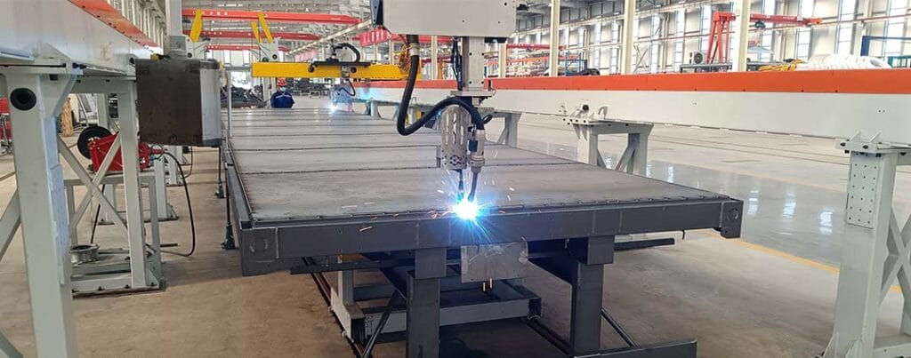
An automatic welding machine is designed to control the welding process with less dependence on continuous manual torch movement. Depending on the system, it may automate torch travel, workpiece rotation, wire feeding, seam detection, welding parameters, or the complete production sequence.
However, automation does not guarantee quality by itself. A machine can repeat the same movement accurately and still produce inconsistent welds if the joint gap changes, the workpiece shifts, the fixture lacks rigidity, or the selected welding parameters do not match the material.
The most successful installations treat the automatic welding machine as part of a complete production system. The workpiece design, joint preparation, fixture, welding source, movement mechanism, sensors, controller, and inspection process must work together.
This guide explains:
- What an automatic welding machine does
- The main machine configurations used in production
- Which welding tasks are suitable for automation
- How fixtures and seam variation affect quality
- When robots, positioners, and vision systems are required
- How to compare automatic and manual welding
- What to evaluate before introducing a new system
What Is an Automatic Welding Machine?
An automatic welding machine is a system that performs one or more welding operations according to a controlled sequence. It may move the welding torch along a programmed path, rotate the workpiece beneath a fixed torch, or coordinate both movements.
The machine can also control supporting functions such as:
- Arc starting and stopping
- Welding current and voltage
- Wire feeding
- Shielding gas delivery
- Torch travel speed
- Workpiece positioning
- Seam searching
- Oscillation or weaving
- Multi-pass path execution
- Cooling time
- Fault monitoring
The wider concept of welding includes processes that join materials through heat, pressure, or a combination of both. An automatic system adds controlled motion, repeatable process parameters, and programmed sequencing to the selected welding method.
Some machines are designed around one product and one seam. Others use multi-axis robots, interchangeable fixtures, stored programs, and sensing systems to process a wider product range.
This difference is important. A highly dedicated machine may offer simple and stable production for one component, while a flexible robotic cell may be more appropriate when products, seam positions, and batch sizes change regularly.
How an Automatic Welding Machine Works
Although machine designs vary, most automated welding cycles follow a similar sequence.
Workpiece loading
The operator, conveyor, handling robot, or transfer device places the components into the fixture. The fixture locates them against defined reference surfaces and holds them in position.
At this stage, the system may confirm:
- The correct part is present
- The part orientation is correct
- All required components have been loaded
- Clamps have reached their locked positions
- The protective enclosure is secure
- The welding area is ready
Joint positioning
The machine moves the torch, workpiece, or both into the starting position.
In a dedicated system, this may involve a linear slide, rotating chuck, column-and-boom structure, or powered positioner. In a robotic system, several axes coordinate to place the torch at the programmed angle and distance.
Welding parameter activation
The controller calls the required welding procedure. Parameters may include current, voltage, travel speed, wire-feed speed, gas flow timing, weave pattern, pulse settings, and crater-fill behavior.
Different sections of one joint may use different parameter sets. For example, the system may reduce speed at the start, increase it along the stable middle section, and use a controlled end sequence to prevent a crater defect.
Path execution
The machine follows the programmed seam while maintaining the required relationship between the torch and workpiece.
A basic system repeats a fixed path. A more advanced automatic welding machine may search for the seam before welding or adjust its path during the process.
Completion and inspection
After the arc stops, the machine may return to a safe position, release the clamps, rotate the workpiece, or begin another weld.
The completed part may then move to visual inspection, dimensional checking, destructive testing, nondestructive examination, or the next manufacturing stage.
Main Types of Automatic Welding Machines
The term automatic welding machine covers several equipment categories. Choosing the right configuration begins with understanding how the seam and workpiece need to move.
Fixed-torch welding machine
In a fixed-torch system, the welding torch remains largely stationary while the workpiece moves beneath it.
This configuration is often used for circular seams, longitudinal seams, pipes, cylinders, tanks, flanges, and regularly shaped components.
Its main advantage is mechanical simplicity. If the workpiece can be rotated or translated accurately, the machine may not require a complex multi-axis torch system.
However, it is less flexible when the product contains seams at several angles or positions.
Linear seam welding machine
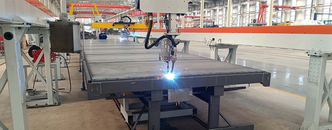
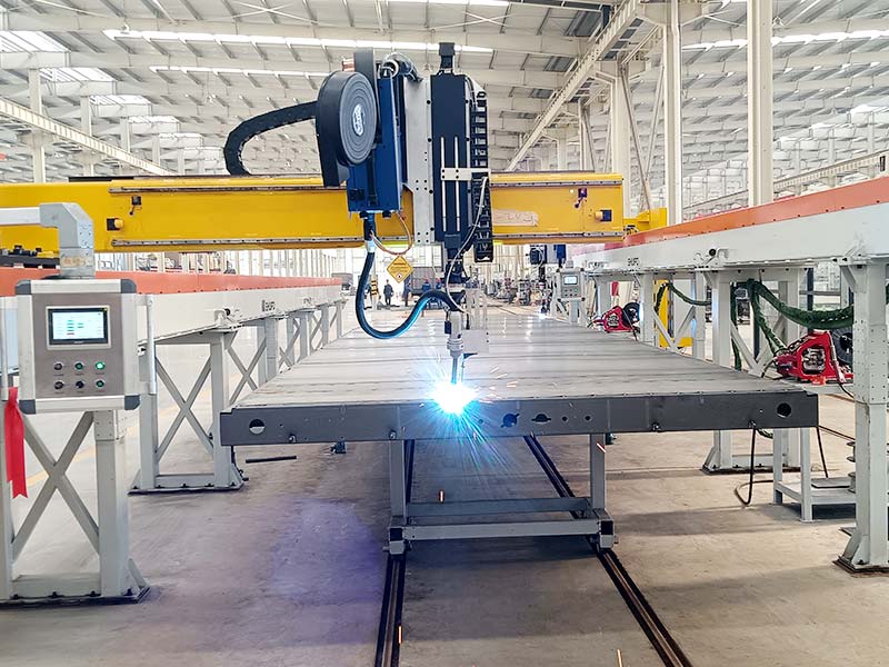
A linear system moves the torch or workpiece along a straight guide.
It is suitable for:
- Longitudinal seams
- Straight butt joints
- Panel welding
- Beam components
- Tank sections
- Repetitive edge joints
A rigid guide can provide stable travel speed and torch position. The main requirement is that the joint remains straight and consistently located.
Circumferential welding machine
This machine rotates a round workpiece while the torch follows a circular joint.
Typical applications include:
- Pipe-to-flange connections
- Cylindrical vessels
- Rings
- Round covers
- Sleeves
- Wheel-shaped components
The chuck, rollers, or positioner must rotate the workpiece smoothly. Eccentricity or incorrect clamping can cause the seam to move relative to the torch.
Welding positioner system
A positioner supports and rotates the workpiece so that the joint remains in a suitable welding orientation.
The torch may be manually adjusted, mechanically controlled, or mounted on a robot. Positioners are useful for frames, boxes, structural components, and multi-sided assemblies.
They can improve torch access and reduce the need to weld in difficult orientations.
Robotic welding cell
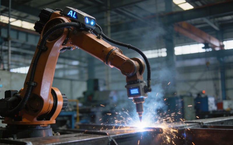
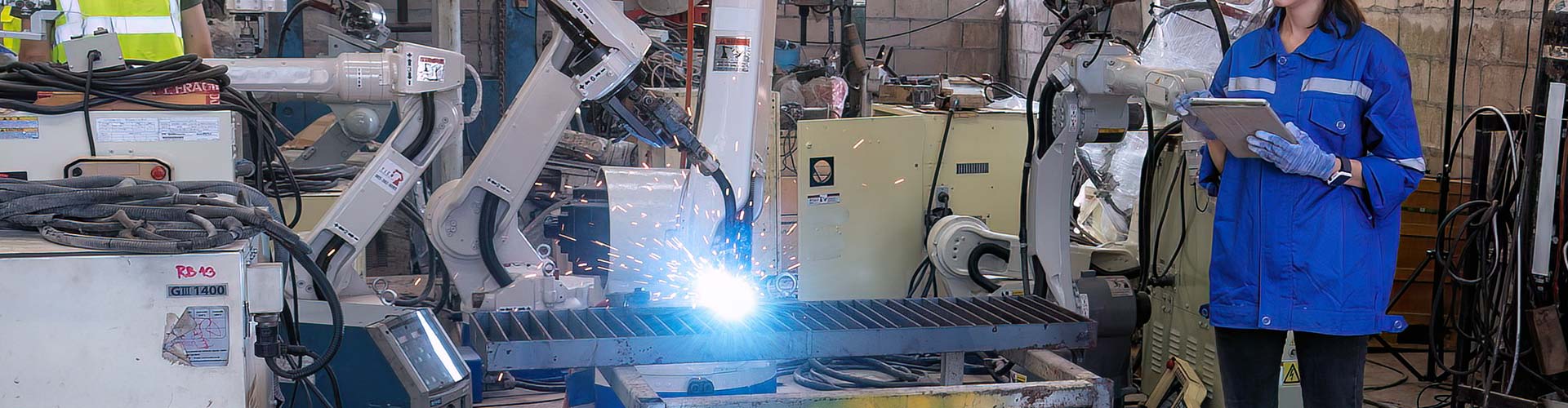
A robotic cell uses a multi-axis industrial or collaborative robot to guide the torch through straight, curved, angled, or three-dimensional paths.
A robotic automatic welding system is suitable when one workstation must process multiple seams, product models, or joint orientations.
The robot provides movement flexibility, but the system still requires suitable fixtures, process control, torch access, and workpiece consistency.
Vision-guided welding machine
A vision-guided system scans the workpiece to identify joint position or surface geometry.
It may correct a stored program, calculate a new path, or track the seam during welding. This is valuable for large components, variable assemblies, and products that cannot be positioned identically with a basic fixture.
Vision increases adaptability, but it does not replace correct material preparation and sound welding procedures.
Automatic Welding Machine Comparison
| Machine type | Best-suited work | Main strength | Main limitation | Critical selection factor |
|---|---|---|---|---|
| Fixed-torch machine | Round or regularly moving parts | Simple, stable mechanical structure | Limited path flexibility | Workpiece motion accuracy |
| Linear seam machine | Straight continuous joints | Consistent travel speed | Mainly suited to linear seams | Joint straightness |
| Circumferential machine | Pipes, rings, and cylindrical parts | Stable circular welding | Requires accurate rotation | Workpiece concentricity |
| Positioner-based system | Multi-sided fabricated parts | Improves welding orientation | Requires suitable clamping | Load balance and rotation range |
| Robotic welding cell | Multiple products and complex seams | Flexible multi-axis movement | More integration planning | Reach, fixture, and programming |
| Vision-guided system | Variable or irregular workpieces | Compensates for seam variation | More sensing and control complexity | Scan quality and joint detectability |
Which Welding Tasks Are Suitable for Automation?
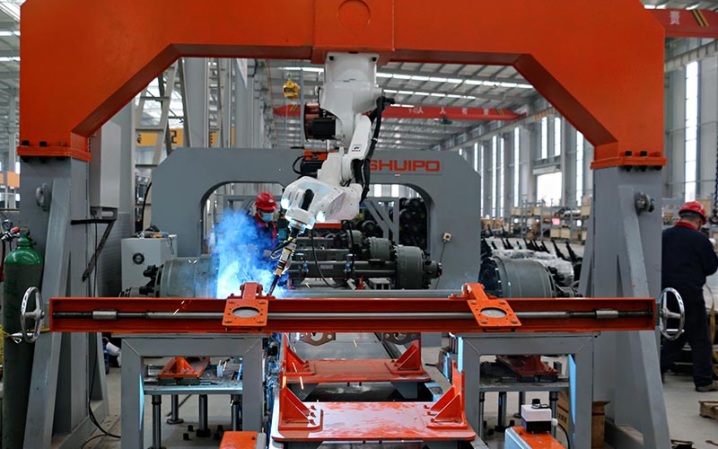
An automatic welding machine performs best when the task contains repeated and measurable conditions.
Repetitive straight seams
Straight seams are strong candidates because the travel path is easy to define. A linear axis or robot can maintain stable speed and torch orientation.
The main risks are joint gap variation, part movement, and distortion along long welds.
Circular joints
Circular seams can be automated by rotating the workpiece beneath a fixed torch or moving a robot around the component.
The correct choice depends on the workpiece size, balance, weight, and surrounding geometry.
Repeated fillet welds
Fillet joints on frames, brackets, stiffeners, and structural components are commonly automated.
The machine must maintain a suitable work angle between both surfaces. If one component changes position, the arc may no longer remain centered in the joint.
Groove welds
Prepared grooves can be welded automatically when the root gap, bevel angle, and alignment remain controlled.
Thicker joints may require multiple passes. Each pass needs a defined path, offset, torch angle, and process setting.
Long continuous joints
Automation is useful for long welds because it can maintain travel speed more consistently than continuous manual movement.
However, the system must manage heat accumulation and workpiece distortion. A mechanically accurate path is not enough if the seam moves during welding.
Complex three-dimensional seams
Multi-axis robots can follow curved and angled joints while changing torch orientation.
These applications require careful path planning, reach analysis, collision checking, and sometimes coordinated workpiece movement.
High-mix components
Frequently changing products were traditionally difficult to automate because each variation required new programming and fixtures.
Modern systems using stored programs, modular tooling, offline programming, and vision can reduce changeover work. A collaborative robot workstation may also support flexible welding tasks through simplified programming and adaptable workstation layouts.
The Difference Between Automatic, Mechanized, and Robotic Welding
These terms are sometimes used interchangeably, but they describe different levels of process control.
Mechanized welding
In mechanized welding, a machine controls part of the movement, but an operator may still initiate, monitor, adjust, or stop the process.
For example, a carriage may move the torch along a straight seam while the operator controls positioning and welding parameters.
Automatic welding
An automatic welding machine completes the programmed sequence with limited operator intervention during the weld.
The system can coordinate movement, arc control, parameter changes, and cycle completion.
Robotic welding
Robotic welding is a form of automatic welding that uses a programmable multi-axis robot to move the torch or workpiece.
The main advantage is motion flexibility. The same robot can process seams in different locations and orientations if the workpiece and program are correctly prepared.
Adaptive welding
Adaptive systems use sensors to modify the process according to actual conditions.
The system may correct path position, change travel speed, adjust weaving, or select parameters based on detected joint geometry.
The highest level of complexity is not automatically the best choice. A simple linear machine may be more stable for one permanent seam, while a robotic or adaptive solution may be more valuable for changing products.
Core Components of an Automatic Welding Machine
The performance of an automatic welding machine depends on the interaction of several subsystems.
Welding power source
The power source generates and controls the electrical output required for the selected process.
It should support the required material, thickness, deposition rate, arc characteristics, and communication method.
Stable power delivery is essential, but it must be matched with correct wire feeding, torch movement, shielding, and joint preparation.
Welding torch
The torch delivers current, filler wire, and shielding gas to the joint.
Its size and shape affect access. A torch that is suitable for an open joint may not fit inside a narrow frame or deep corner.
The torch must also manage heat during long automatic cycles.
Motion system
The motion system may include:
- Linear rails
- Rotating chucks
- Servo axes
- Positioners
- Robot arms
- Gantries
- Column-and-boom systems
- External tracks
Movement must be smooth enough to maintain stable travel speed and accurate enough to keep the arc in the required location.
Wire-feeding system
Consistent wire feeding helps maintain arc stability and deposition.
The wire path, drive rolls, liner, contact tip, spool location, and cable routing all affect performance. Long or sharply curved wire paths can create feeding resistance.
Fixture
The fixture establishes the relationship between the real joint and the programmed path.
Its role is not simply to hold the part. It must locate components repeatably, resist welding forces, control movement, allow torch access, and support practical loading.
Controller
The controller coordinates movement, welding parameters, clamping, sensors, alarms, and safety conditions.
A well-designed control interface should make it easy to select programs, identify faults, confirm system status, and manage production changes.
Sensors
Sensors may confirm:
- Part presence
- Clamp position
- Torch position
- Gas availability
- Wire condition
- Seam location
- Arc status
- Cooling condition
- Safety-zone status
The system should respond to faults before they produce repeated defective welds.
Why Fixture Design Determines Welding Consistency
A robot or servo system may return to the same programmed coordinates repeatedly, but it cannot guarantee that the physical joint is still located there.
This difference between machine repeatability and workpiece repeatability is one of the most important concepts in automatic welding.
Reliable datum control
Each part should contact clearly defined locating surfaces. These datums establish where the machine expects the joint to be.
If operators position parts against different surfaces from cycle to cycle, the seam can move even when the fixture appears closed.
Adequate clamping force
Clamps must prevent components from moving during tack welding, heating, and cooling.
However, excessive force can deform thin components before welding begins.
Torch clearance
Clamp arms, support blocks, cylinders, and fixture frames should not block the torch.
The complete torch body and cable path must be considered, not only the programmed tool point.
Distortion management
Fixtures cannot always hold a part completely rigid because thermal expansion creates significant internal force.
A practical fixture balances restraint with controlled movement. The welding sequence may also alternate sides or divide long seams to reduce distortion.
Loading repeatability
A technically accurate fixture may still perform poorly if loading is complicated.
Operators need clear part orientation, mistake-proof locating features, visible clamp status, and safe access.
Good fixture design improves both welding quality and production consistency.
How Seam Variation Affects Automatic Welding
An automatic welding machine follows known conditions. When the actual joint changes, the process can move outside its acceptable range.
Common seam variations include:
- Changing root gap
- Unequal edge height
- Inconsistent overlap
- Variable bevel angle
- Distorted components
- Incorrect tack position
- Surface contamination
- Joint movement during heating
- Dimensional accumulation across an assembly
A small variation may have little effect on a wide fillet weld but create a serious problem in a narrow root pass.
The acceptable variation depends on the process, material, joint type, wire diameter, torch angle, penetration requirement, and quality criteria.
Fixed-path welding
A fixed path is appropriate when fixtures and upstream manufacturing keep the seam within a narrow positional range.
This is often the simplest and fastest approach.
Pre-weld seam searching
The machine measures reference points before starting. It then shifts or rotates the programmed path to match the detected part.
This works well when the entire joint has moved but its shape remains predictable.
Real-time seam tracking
A sensor observes the joint immediately before or during welding. The controller corrects the path as the seam changes.
Tracking is useful for long seams, formed components, and assemblies affected by distortion.
Automatic path generation
A 3D scan can be used to recognize joint geometry and calculate a welding trajectory.
This approach can reduce conventional teaching for variable or complex products, although successful detection still depends on visible and distinguishable joint features.
Automatic Welding Machine vs Manual Welding
Manual and automatic welding each have appropriate applications.
| Evaluation factor | Automatic welding machine | Manual welding |
| Repetitive path control | Highly consistent after validation | Depends on operator movement |
| Product variation | Requires programs, tooling, or sensing | Operator can adapt directly |
| Long continuous seams | Maintains stable programmed travel | Can be physically demanding |
| Complex access | Depends on machine reach and torch clearance | Skilled welder may adjust posture |
| Joint variation | Requires tolerance control or sensing | Welder can compensate in real time |
| Production records | Easier to collect system data | Often requires manual recording |
| Changeover | Depends on fixture and programming design | Can be faster for one-off work |
| Repeatability | Strong under controlled conditions | Depends on skill and fatigue |
| Initial process development | Requires structured validation | Can begin with less integration |
| Best-fit production | Repeated or measurable welding tasks | Repair, prototypes, and highly variable work |
The practical choice is not always complete automation or complete manual production.
Many facilities use a mixed strategy. Automatic systems handle repetitive, long, or physically demanding seams, while skilled welders manage repairs, unusual joints, and low-volume work.
How to Control Weld Quality
Quality control begins before the machine starts welding.
Standardize joint preparation
Cutting, machining, forming, and tack assembly should produce predictable joint geometry.
Automation will repeat defects from upstream processes unless those processes are controlled.
Validate welding parameters
Parameters should be established using representative production parts.
The procedure should consider:
- Material type
- Material thickness
- Joint geometry
- Welding position
- Required penetration
- Bead shape
- Heat input
- Travel speed
- Filler material
- Shielding conditions
Monitor consumables
Contact tips, nozzles, liners, wire, and shielding components gradually wear or become contaminated.
A program that worked correctly with new consumables may produce unstable results after wear changes the wire position or gas coverage.
Control the torch center point
In robotic systems, the controller assumes that the torch tip remains in a defined geometric position.
A bent torch neck, worn contact tip, collision, or incorrect replacement can shift this point and move every programmed weld.
Manage spatter
Spatter buildup can restrict gas flow, change the electrical contact condition, interfere with sensing, and affect torch access.
Cleaning systems and scheduled maintenance help keep the automatic welding machine within its validated condition.
Inspect trends, not only failed parts
Quality monitoring should identify gradual changes before they create major defects.
Useful indicators may include arc interruptions, wire-feed alarms, seam-correction values, cycle interruptions, consumable life, rework frequency, and inspection results.
Common Problems and Their Causes
The weld path misses the joint
Possible causes include inaccurate loading, fixture wear, component variation, incorrect program selection, shifted tool calibration, or tack-weld distortion.
Changing the robot program without finding the source may only move the problem to another part.
Weld penetration is inconsistent
This may result from changing gaps, unstable current delivery, incorrect travel speed, workpiece contamination, poor grounding, or variation in torch distance.
The complete process should be checked rather than adjusting one parameter in isolation.
The machine produces acceptable first parts but later quality declines
Consumable wear, heat buildup, nozzle contamination, fixture movement, or wire-feeding resistance may develop during production.
Warm equipment may also behave differently from the first cycle after startup.
The arc starts unreliably
Possible causes include poor electrical contact, contaminated material, incorrect wire extension, worn contact tips, unstable grounding, or incorrect start parameters.
The starting point should be accessible and consistently prepared.
The workpiece distorts after welding
Automatic movement does not eliminate thermal distortion.
The welding sequence, clamping, heat input, joint design, tack pattern, and cooling process should be reviewed together.
Frequent collisions occur
Collisions may result from incorrect part loading, poor fixture clearance, program errors, unexpected seam correction, cable interference, or an incorrect tool model.
Collision recovery should include inspection of the torch and tool calibration before production restarts.
How to Choose an Automatic Welding Machine
A structured selection process helps prevent over-automation and under-designed systems.
Step 1: Classify the products
Record product dimensions, weights, materials, joint types, seam lengths, and annual variation.
Group similar components according to how they can be fixtured and welded.
Step 2: Measure real workpiece variation
Do not base the project on one specially prepared sample.
Measure normal differences in gap, position, straightness, tack assembly, forming, and surface condition.
Step 3: Define the required flexibility
Determine whether the machine will process one product, one product family, or frequently changing components.
This decision strongly affects the choice between dedicated automation and robotic equipment.
Step 4: Review torch access
Check the entire welding path for interference from the workpiece, fixture, clamps, cables, and surrounding equipment.
A seam may be visible but still impossible to weld at the required angle.
Step 5: Select the motion concept
Decide whether the torch should move, the workpiece should move, or both should move together.
The simplest reliable motion arrangement is usually preferable to unnecessary mechanical complexity.
Step 6: Determine the sensing level
Stable parts may need only presence sensors and fixed programs.
Variable products may require seam searching, tracking, vision, or adaptive process control.
Step 7: Plan inspection and data collection
Define how completed welds will be checked and which process conditions should be recorded.
Inspection requirements should influence machine design from the beginning.
Step 8: Validate representative production
Testing should include:
- Normal dimensional variation
- Different operators loading the fixture
- Cold and warm equipment conditions
- Maximum seam length
- Difficult joint locations
- Expected consumable wear
- Production-representative surfaces
- Repeated cycles
- Fault and recovery conditions
A successful demonstration weld is useful, but repeated production stability is the real objective.
When a Dedicated Machine Is Better Than a Robot
A dedicated automatic welding machine may be the stronger solution when:
- The product remains unchanged
- The seam is straight or circular
- The joint position is highly repeatable
- Production volume is stable
- Changeover is limited
- A simple motion system can reach the full seam
- The fixture can control the workpiece accurately
A robotic system may be more appropriate when:
- Several seam orientations are required
- The product family changes
- The workpiece has curved or three-dimensional paths
- Multiple welds must be completed in one loading
- Future products are expected
- Flexible programming is important
- External positioners can improve access
The decision should be based on lifecycle production needs rather than the appearance or complexity of the equipment.
Building a Reliable Welding Process
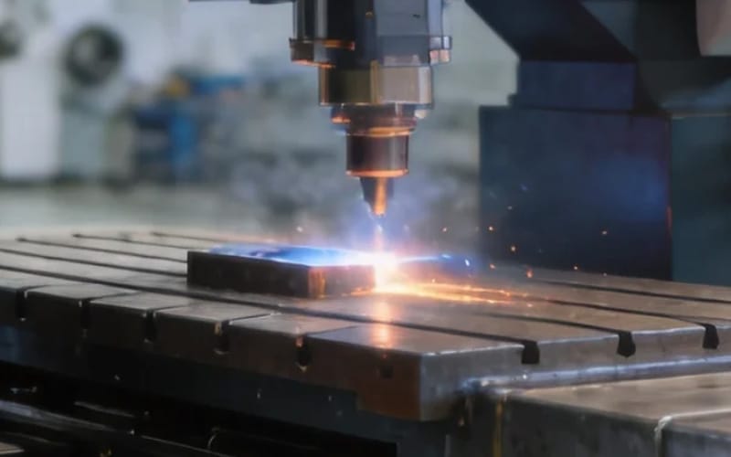
A high-quality automatic welding machine project usually follows a disciplined engineering sequence.
First, the production team defines the required joint quality and identifies normal workpiece variation.
Second, the fixture and motion system are designed around actual parts rather than ideal drawings alone.
Third, welding procedures are developed and tested under representative conditions.
Fourth, sensors and controls are added only where they solve defined production problems.
Finally, operators and maintenance personnel receive clear standards for loading, consumable replacement, calibration, inspection, and fault recovery.
This approach creates a process that can be understood, maintained, and improved. It is more reliable than depending on complex equipment to compensate for uncontrolled upstream manufacturing.
Conclusion
An automatic welding machine can improve travel consistency, process repeatability, production control, and operator working conditions. It can handle straight seams, circular joints, fillet welds, groove welds, long continuous paths, and complex robotic trajectories.
Its success depends on more than the welding unit itself. Joint preparation, fixtures, torch access, workpiece tolerance, motion accuracy, consumables, sensors, programming, inspection, and maintenance all influence the final result.
Dedicated machines are often effective for stable, repetitive products. Robotic and vision-guided systems provide more flexibility for changing components and complex paths.
The best system is not the one with the greatest number of automated functions. It is the automatic welding machine that matches the real product, controls the important sources of variation, and maintains reliable weld quality throughout normal production.
FAQ
What is an automatic welding machine?
An automatic welding machine controls torch or workpiece movement and performs welding according to a programmed cycle. It may also manage wire feeding, welding parameters, clamps, positioners, seam detection, and safety functions. Designs range from dedicated linear systems to flexible robotic cells.
Which joints can an automatic welding machine handle?
It can process butt joints, lap joints, T-joints, corner joints, edge joints, fillet welds, groove welds, circular seams, and curved paths. Suitability depends on torch access, joint preparation, fixture accuracy, seam variation, material thickness, and the need for single- or multi-pass welding.
Is an automatic welding machine suitable for small batches?
It can be suitable when changeover is fast and the system uses flexible programming, modular fixtures, stored procedures, or vision-based path correction. A highly dedicated machine may be less practical for frequent product changes, while a robotic system can support a broader product family.
Why does an automatic welding machine miss the seam?
Common causes include inconsistent loading, worn fixtures, dimensional variation, incorrect programs, torch calibration errors, tack-weld distortion, or movement during heating. Seam searching and tracking can compensate for limited variation, but the underlying manufacturing process should also be checked.
How can automatic welding quality remain consistent?
Use controlled joint preparation, repeatable fixtures, validated parameters, stable wire feeding, correct shielding, routine torch calibration, consumable maintenance, and representative inspections. Process trends should be reviewed regularly so gradual changes are corrected before repeated defects occur.