
Оглавление
Введение
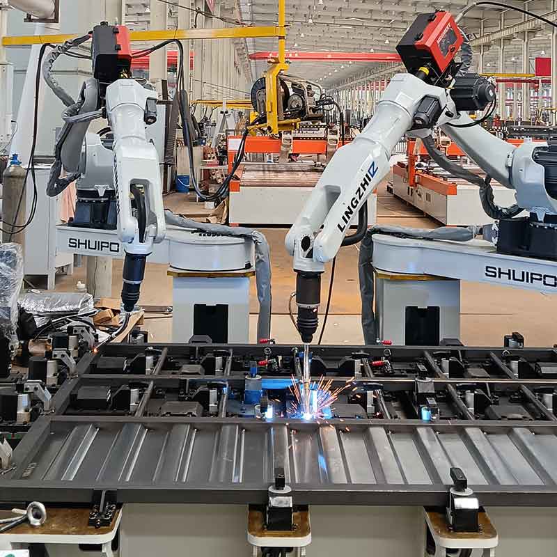
Сварочные промышленные роботы могут обрабатывать наиболее распространенные конфигурации сварных соединений, включая стыковые соединения, стыковые соединения, Т-образные соединения, угловые соединения, краевые соединения, канавочные сварные швы, угловые сварные швы, изогнутые швы и многопроходные соединения. Однако распознавание типа соединения - это только начало решения по автоматизации.
Робот может быть физически способен достичь соединения, но при этом не может произвести стабильный сварной шов, если детали перемещаются, зазор меняется, угол горелки ограничен или запрограммированный путь не соответствует реальному шву. Таким образом, успешная роботизированная сварка зависит от полной взаимосвязи между геометрией соединения, подготовкой заготовки, точностью крепления, движением робота, параметрами сварки и сенсорной технологией.
Термин сварочное соединение описывает геометрическое расположение соединяемых компонентов. в автоматизированном производстве эта геометрия определяет, как робот приближается к шву, может ли факел поддерживать подходящий угол и насколько легко можно расположить соединение от одной заготовки к другой.
Ключевые моменты, затронутые в настоящем руководстве, включают в себя
- Пять основных семейств сварных соединений, с которыми могут справиться промышленные роботы
- Разница между угловыми сварными швами и канавочными сварными швами
- Почему некоторые просто выглядящие суставы трудно автоматизировать
- Как приспособления и допуски деталей влияют на консистенцию сварного шва
- Когда становится необходимым отслеживание швов или 3D-видение
- Как оценить соединение перед инвестированием в роботизированную сварку
Почему геометрия сварного соединения важна для производительности роботов
Опытный сварщик непрерывно интерпретирует соединение во время сварки Сварщик может заметить изменяющийся зазор, немного изменить угол горелки, уменьшить скорость движения, отрегулировать положение дуги или компенсировать деталь, которая была собрана несовершенно.
Обычный робот не делает эти настройки автоматически Он следует запрограммированному пути и параметрам работы, если только датчики или адаптивные функции управления не предоставляют новую информацию, Именно поэтому сварка промышленных роботов работает лучше всего, когда геометрия соединения предсказуема и повторяема.
Практический способ оценки косяка - задать четыре вопроса
Виден или обнаруживаем шов?
Робот-контроллер должен знать, где начинается сварной шов, где он заканчивается и как меняется соединение между этими точками Четко определенный прямой шов легче автоматизировать, чем соединение, скрытое за другим компонентом.
Может ли факел правильно добраться до сустава?
Достижения шва недостаточно. робот также должен поддерживать необходимый рабочий угол, угол перемещения, расстояние между кончиками контактов и работой и зазор кабеля по всему сварному шву.
Соединение остается в прежнем положении?
Если каждый узел размещает шов по-разному, фиксированная программа робота может больше не соответствовать реальному соединению. Могут потребоваться более качественные приспособления, улучшенное производство на входе или технология размещения швов.
Можно ли контролировать тепло и искажения?
Длинные сварные швы, тонкие компоненты, асимметричные соединения и многоходовые канавки могут искажаться по мере продвижения сварки. Последовательность робота, метод зажима, движение позиционера и ввод тепла должны планироваться вместе.
Эта оценка, состоящая из четырех частей, часто более полезна, чем просто вопрос, может ли робот сварить определенное название соединения.
Основные типы сварных соединений Сварка Промышленные роботы могут справиться
Большинство промышленных сварных узлов построены из пяти основных семейств соединений. сварочные промышленные роботы обычно могут обрабатывать все пять, но каждый из них предъявляет разные требования к автоматизации.
Соединения
Стыковое соединение образуется, когда два компонента встречаются с края до края, обычно в одной плоскости. стыковые соединения широко используются в пластинах, панелях, рамах, резервуарах, трубах, конструктивных секциях и изготовленных корпусах.
Прямые стыковые соединения являются одними из самых простых для программирования швов, когда края точно подготовлены и корневой зазор остается постоянным. робот может следовать по линейной траектории, сохраняя при этом контролируемую скорость и ориентацию факела.
Однако стыковые соединения становятся более требовательными, когда
- Корневое отверстие измен етс по шву
- Края пластин смещены
- Требования к проникновению высоки
- Сварка должна быть завершена с двух сторон
- Требуется несколько слоев или проходов
- Тепловые искажения изменяют положение шва
Для более толстых материалов подготовка кромок может создавать канавки V-, U-, J- или скошенные. Эти соединения могут потребовать нескольких проходов сварки, рисунков плетения, отслеживания шва или изменения положения заготовки.
Основным риском автоматизации стыкового соединения обычно не является сам путь. Это изменение условий зазора, выравнивания, подготовки скоса и проникновения.
Соединения круга
При нахлестном соединении создают, когда один компонент перекрывает другой Сварной шов обычно размещают вдоль одного или обоих открытых краев перекрывающегося материала.
Соединения внахлест распространены в листовых сборках, кронштейнах, шкафах, компонентах транспортных средств, армирующих пластинах, крышках и изготовленных рамах. Их можно сваривать угловыми сварными швами, точечными сварными швами, сварными швами или другими процессами в зависимости от конструкции.
Сварочные промышленные роботы хорошо справляются с нахлестными соединениями, когда:
- Размер перекрытия является последовательным
- Обе поверхности остаются в тесном контакте
- Верхняя кромка может быть надежно расположена
- Факел имеет достаточный зазор
- Подаваемое тепло соответствует толщине материала
Переменный зазор между перекрывающимися листами может влиять на проникновение и форму борта. На тонких материалах чрезмерное тепло также может вызвать прожог или искажение. поэтому приспособления должны сжимать детали вместе, не блокируя путь сварки.
Открытый край дает роботу полезную геометрическую привязку, но только тогда, когда этот край остается в предсказуемом положении.
Т-образные соединения
Т-образное соединение образуется, когда один компонент встречается с другим примерно под прямым углом, создавая Т-образное поперечное сечение. Соединение обычно сваривается одним или двумя угловыми сварными швами.
Т-образные соединения широко используются в ребрах жесткости, основаниях оборудования, балках, рамах, кронштейнах, конструктивных узлах, ребрах, опорах и компонентах машин. Их повторяющиеся прямые швы делают их сильными кандидатами для роботизированной сварки.
Основная проблема - доступ факела вблизи перекрестка. робот должен направить дугу в корень сустава, сохраняя при этом правильный угол между обеими поверхностями. если угол факела слишком мал, сплавление может стать неравномерным. если он слишком крутой, факел или сопло могут помешать заготовке.
Когда обе стороны Т-образного соединения требуют сварки, позиционер может вращать узел, поэтому каждый шов представлен в более стабильном положении сварки. Это может уменьшить трудные движения запястья и улучшить доступ к корню сустава.
Т-образные соединения очень подходят для автоматизации, но их качество во многом зависит от посадки, зажима и способности поддерживать постоянную связь между вертикальными и горизонтальными компонентами.
Угловые Соединения
Угловые соединения соединяют два компонента на их краях или вблизи них, обычно образуя открытый или закрытый угол. они распространены в коробках, шкафах, контейнерах, рамах, панелях, корпусах и готовых корпусах.
Робот может сваривать как внутренние, так и внешние угловые соединения. Внешние углы часто легче достичь, в то время как внутренние углы могут ограничить угол факела и создать риск столкновения.
К важным факторам относятся
- Расстояние между корпусом факела и прилегающими поверхностями
- Независимо от того, открыт ли сустав, закрыт или частично перекрыт
- Толщина материала
- Требуемое проникновение сварного шва
- Степень искажений, которую может выдержать угол
Тонкие угловые соединения могут быть особенно чувствительны к теплу Даже когда робот точно следует по пути, чрезмерная подача тепла может привести к тому, что края будут стягиваться, раздвигаться или терять точность размеров.
Поэтому сбалансированная последовательность сварки и стабильный план зажима необходимы. Для изделий коробчатой формы может быть лучше сваривать противоположные углы поэтапно, а не завершать одну сторону перед переходом к следующей.
Краевые соединения
Краевой стык размещает два параллельных края рядом друг с другом и соединяет их вдоль общего края. Такая конфигурация часто встречается в листовом металле, фланцевых компонентах, легких корпусах, крышках и деталях, которые не несут тяжелую нагрузку через стык.
Краевые соединения обычно обеспечивают хорошую видимость пути, но они могут быть чувствительны к:
- Неравная высота кромок
- Тонкий материал
- Непоследовательное расстояние между краями
- Проплавление
- Локальное искажение
- Плохой зажим вблизи шва
Сварочные промышленные роботы могут эффективно обрабатывать краевые соединения при совмещении и опоре кромок Повторяемость робота полезна для создания ровного борта, но процедура сварки должна предотвращать чрезмерное плавление на открытых кромках.
Краевые соединения следует тщательно оценивать, если готовая деталь имеет строгие требования к размерам или внешнему виду.
Таблица совместимости сварных соединений
| Тип сустава | Типичная роботизированная пригодность | Основная форма сварки | Основное преимущество автоматизации | Первичный инженерный риск |
|---|---|---|---|---|
| Стыковое соединение | Высокий уровень и последовательная подготовка | Пазовой сварной | Четкий и часто линейный путь сварки | Переменный корневой зазор или несоосность |
| Коленчатый сустав | Высокий | Филе, пятно или штекерная сварка | Открытый край обеспечивает ссылку на путь | Разрыв между перекрывающимися компонентами |
| Т-образное соединение | Высокий | Филе сварного | Повторяющиеся швы и стабильная геометрия | Ограниченный доступ к факелу у корня |
| Угловой шарнир | От среднего до высокого | Филе или пазовой сварной шов | Подходит для коробок и изделий в рамке | Искажение и внутренний зазор |
| Кромкообразный сустав | От среднего до высокого | Кромка или канавка сварного | Простой путь шва | Прогон и движение кромки |
| V-образное соединение | Высокий уровень планирования процессов | Многопроходной пазовой сварной | Предсказуемая геометрия канавок | Управление последовательностью прохождения и наполнителем |
| U- или J-образное соединение | От среднего до высокого | Многопроходной пазовой сварной | Уменьшение объема канавки на толстых деталях | Комплексная подготовка и доступ к боковинам |
| Изогнутый сустав | От среднего до высокого с помощью зондирования | Филе или пазовой сварной шов | Робот может повторять сложные траектории | Калибровка пути и изменение ориентации |
| Пересекающийся сустав | Проектно-зависимый | Комбинированные типы сварных швов | Несколько швов могут быть интегрированы в один цикл | Риск столкновения и недоступные переходы |
Вариации пазов и требования к их автоматизации
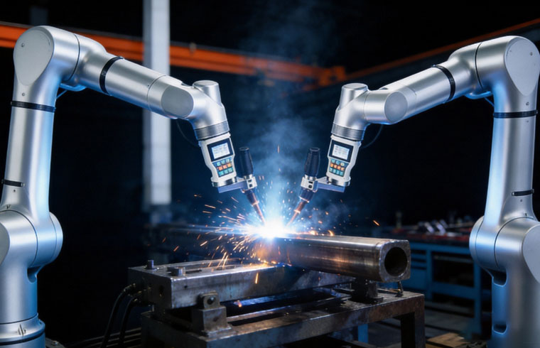
Пазовые соединения не являются отдельным базовым семейством соединений. это подготовленные формы, чаще всего применяемые к стыковым соединениям, которые позволяют процессу сварки проникать глубже в материал.
Квадратные соединения пазов
В квадратной канавке используются прямые неподготовленные края. ее относительно просто запрограммировать, поскольку робот обычно следует по одному прямому пути.
Его пригодность для автоматизации зависит от толщины материала, корневого зазора, требований к проникновению, а также от того, выполняется ли сварка с одной или обеих сторон. Если зазор непоследователен, роботу может потребоваться отслеживание шва или адаптивная регулировка параметров.
Соединения V-Groove и Bevel-Groove
V-образная канавка создается путем подготовки обоих краев, а коническая канавка обычно подготавливает одну сторону. Эти конструкции обеспечивают лучший доступ к корню соединения на более толстых компонентах.
Сварочные промышленные роботы могут завершить эти соединения несколькими проходами. Каждый проход требует своего пути, смещения, угла горелки, направления движения и параметров процесса.
Корневой проход обычно имеет наименьший допуск для ошибки позиционирования, Заполнение и проходы крышки могут потребовать ткачества или управления боковины, робот программа также должна учитывать изменение профиля канавки, как осажденный металл сварного шва заполняет соединение.
Конфигурация с двойным V может потребовать поворота заготовки, чтобы сварка могла быть завершена с обеих сторон. Программируемый позиционер часто имеет ценность в этой ситуации.
Соединения U-Groove и J-Groove
В U- и J-канавках используются препараты с изогнутыми краями. Их часто выбирают, когда требуется глубокое соединение, но необходимо контролировать количество наплавленного металла сварного шва.
Эти соединения подходят для роботизированной сварки, но они требуют тщательной ориентации горелки. робот должен поддерживать доступ к стенкам канавки и корню, не позволяя корпусу горелки или соплу контактировать с заготовкой.
Поскольку форма канавки меняется на глубину, планирование пути может быть более сложным, чем для простой V-образной канавки. Многопроходные процедуры должны быть проверены посредством сварки образцов до начала полного производства.
Филеварные швы против пазовых швов в роботизированном производстве
Сварные швы с филе и канавками создают различные проблемы автоматизации.
Филе сварные швы обычно используются в нахлесточных соединениях, Т-образных соединениях и угловых соединениях. Их треугольное поперечное сечение образуется на пересечении двух поверхностей. Они, как правило, хорошо подходят для сварки промышленных роботов, поскольку путь шва часто виден и повторяется.
Основными требованиями являются
- Постоянное пересечение обеих поверхностей
- Подходящие факел для работы и углы перемещения
- Надежный контроль размера ножки сварного шва
- Стабильная посадка по всему шву
- Достаточно места для сопла и корпуса факела
Сварные швы канавок используются, когда соединение требует более глубокого проникновения или подготовленного отверстия между компонентами. Они часто требуют более точного позиционирования пути и могут включать несколько слоев.
Основными требованиями являются
- Точная подготовка кромок
- Контролируемое раскрытие корня
- Стабильное выравнивание
- Правильная последовательность прохождения
- Очистка между проходами при необходимости
- Контроль искажений и накопленного тепла
Галтель сварного шва может показаться проще, но это может стать трудным, когда корень соединения скрыт или вертикальный элемент меняет положение. паз сварного шва может показаться более сложным, но он может быть очень повторяемым, когда подготовка и приспособление жестко контролируются.
Само по себе название сустава не определяет сложность автоматизации. Согласованность производства обычно является решающим фактором.
Могут ли сварочные промышленные роботы обрабатывать изогнутые и сложные соединения?
Современные сварочные промышленные роботы не ограничиваются прямыми швами Многоосный робот может следовать круговыми, изогнутыми, наклонными, сегментированными и трехмерными путями, постоянно меняя свою ориентацию.
Типичные сложные приложения включают в себя
- Круговые швы вокруг труб или фланцев
- Изогнутые швы на танках и готовых снарядах
- Пересечения между трубками и пластинами
- Рамки с повторяющимися угловыми соединениями
- Длинные швы, меняющие направление
- Многоходовые канавки с различными смещениями пути
- Сборки с несколькими типами соединений в один цикл
Робот должен координировать свое положение и ориентацию по всему шву. Путь, который кажется гладким сверху, может потребовать серьезного поворота запястья, поскольку рабочий угол меняется вокруг компонента.
A рабочая станция для совместных роботов может поддерживать длинные швы, непрерывную сварку и соединения со сложным углом, когда расположение рабочей станции, охват робота, метод программирования и положение заготовки правильно согласованы.
Сложные соединения также могут потребовать:
- Вращающийся позиционер
- Линейная дорожка
- Дополнительные внешние оси
- Планирование автономного пути
- Моделирование столкновений
- Датчики расположения швов
- Отслеживание в реальном времени
- Скоординированное движение робота и заготовки
Наиболее эффективной стратегией часто является перемещение как робота, так и заготовки. Представление шва в контролируемой ориентации может упростить путь робота и улучшить управление сварочным бассейном.
Как робот достигает и доступ к факелу влияют на совместимость суставов
Соединение может быть автоматизировано только тогда, когда весь сварочный инструмент может получить доступ к нему. инженеры иногда проверяют, может ли запястье робота достичь точки, но не обращают внимания на физический размер горелки, сопла, кабеля, соединения подачи проволоки и окружающей конструкции.
При правильном исследовании вытяжки следует изучить весь шов, а не только его начальную и конечную точки.
Рабочий угол
Угол работы описывает, как факел ориентирован относительно поверхностей, образующих соединение. Т-образные соединения и нахлесточные соединения обычно требуют, чтобы факел делил свой угол между двумя поверхностями.
Угол путешествия
Угол перемещения описывает, как факел наклонен в направлении движения. возможно, этот угол должен оставаться стабильным, поскольку робот следует прямому или изогнутому шву.
Зазор между центром и точкой инструмента
Запрограммированная центральная точка инструмента может достигать шва, даже когда корпус горелки сталкивается с пластиной, элементом жесткости, зажимом или приспособлением. Полная трехмерная модель полезна для выявления этих конфликтов.
Поза запястья
Робот должен избегать неудобных положений запястья, ограничений суставов и внезапных изменений ориентации. Технически достижимый шов все равно может создавать нестабильное движение, если робот должен пройти близко к единственному положению.
Поведение кабеля
Кабели факела и линии обслуживания должны двигаться без улавливания, скручивания или контакта с горячими поверхностями. маршрутизация кабеля становится особенно важной на круговых и разнонаправленных путях.
Поэтому при выборе робота следует учитывать полезный охват и ориентацию, а не только максимальный охват, указанный в спецификации.
Требования к конструкции приспособлений и допускам заготовок
Робот следует взаимосвязи между его запрограммированной системой координат и приспособлением. если приспособление не размещает каждую деталь в одном и том же месте, путь сварки будет постепенно отделяться от реального соединения.
Надежное роботизированное сварочное приспособление должно выполнять четыре функции:
Установите четкие ориентиры
Заготовка должна располагаться на стабильных исходных поверхностях. Эти контрольные точки определяют, где робот ожидает соединения.
Удерживайте компоненты без движения
Зажимы должны сопротивляться движению, вызванному нагрузкой, прихваткой сварки, тепловым расширением и сварочными усилиями. деталь, которая смещается во время сварки, больше не может соответствовать пути робота.
Сохранить доступ к факелу
Сильный зажим не полезен, если он блокирует сопло или не позволяет роботу поддерживать необходимый угол. положения зажимов следует пересматривать вместе с моделированием робота.
Разрешить практическую погрузку и раз
Крепление должно поддерживать производство, а не только точность сварки. Операторам необходим достаточный доступ для загрузки деталей, подтверждения ориентации, наложения зажимов, снятия сборки и проверки завершенных сварных швов.
Допуск заготовки следует оценивать на шве, а не только на габаритных размерах изделия. Небольшие изменения в сборке резки, изгиба, формования или прихватки могут накапливаться и вызывать большую ошибку положения шва.
Например, длинная рама может соответствовать ее общему требованию к размерам, в то время как один внутренний элемент жесткости расположен по-разному на каждом блоке. робот будет точно повторять запрограммированный путь, но он может больше не приваривать центр соединения.
Как 3D-видение и отслеживание швов улучшают адаптивность суставов
Крепления должны контролировать столько вариаций, сколько это практически возможно, но не каждый продукт может быть изготовлен с одинаковыми положениями швов. Большие изготовления, формованные компоненты, сборки, сваренные с помощью липкой сварки, и часто меняющиеся продукты могут потребовать сенсорной технологии.
Различные функции зондирования решают разные проблемы.
Предсварной шов расположение
Камера или лазерный датчик сканирует заготовку перед сваркой. система сравнивает обнаруженное соединение с ожидаемой геометрией и регулирует путь до начала дуги.
Этот метод полезен, когда весь шов сдвинулся, но остается стабильным во время сварки.
Сенсорное зондирование
Сварочная проволока или другой зонд контактирует с выбранными поверхностями для расчета фактического положения соединения. сенсорное распознавание может быть эффективным для простых эталонных проверок, хотя и добавляет этапы в цикл.
Отслеживание сквозного дугового шва
Система управления использует изменения сварочных сигналов для оценки местоположения соединения во время выполнения сварного шва. Этот подход обычно связан с подходящими конфигурациями канавок или галтелей и требует стабильных условий процесса.
Лазерное слежение за швами
Лазерный датчик наблюдает за соединением непосредственно перед тем, как факел достигнет его. Затем робот может исправить путь при изменении положения шва.
3D-видение и автоматическое создание путей
Система с визуальным контролем может сканировать более широкую геометрию заготовки, распознавать особенности шва и генерировать или корректировать траектории робота. Это особенно ценно для производства смеси и соединений, которые не могут быть расположены одинаково с помощью базового приспособления.
A безучебная сварочная рабочая станция сочетает в себе трехмерное зрение, распознавание швов и автоматическое планирование пути для обработки прямых линий, угловых соединений, дуг и комбинированных профилей сварных швов с меньшей зависимостью от обычного точечного обучения.
Зрение не устраняет необходимость хорошей подготовки суставов. Оно расширяет способность системы реагировать на измеримые изменения. Чрезмерные зазоры, загрязнение, плохая подготовка кромок, нестабильные прихватки или сильная деформация все еще могут помешать приемлемой сварке.
Общие проблемы при автоматизации различных сварных соединений
Сустав может быть подходящим в теории, но трудным в ежедневном производстве. Несколько повторяющихся проблем объясняют, почему.
Запрограммированный путь правильный, но шов движется
Обычно это указывает на несоответствующие размеры детали, слабый контроль исходных данных, плохую прихватку или движение крепления.
Решение может включать улучшение подготовки к входу, модернизацию приспособления, добавление эталонных проверок или использование технологии определения местоположения шва.
Робот достигает шва, но не может поддерживать угол факела
Это часто происходит в глубоких углах, близко расположенных ребрах жесткости, внутренних рамах или соединениях возле зажимов.
Возможные решения включают изменение конструкции горелки, перемещение зажимов, вращение заготовки, добавление внешней оси или регулировку последовательности соединения.
Первый участок сваривается правильно, но конец смещается из положения
Длинные швы могут искажаться по мере накопления тепла. деталь может перемещаться, даже если она была правильно расположена перед сваркой.
Может потребоваться пересмотренная последовательность, сбалансированная схема сварки, дополнительное ограничение, снижение теплоемкости или стратегия прерывистой сварки.
Размер филе меняется вдоль сустава
Это может быть вызвано изменением зазоров, неравномерным положением компонента, нестабильным углом перемещения, неправильным размещением проволоки или изменением фактического корня соединения.
Процесс следует рассматривать как целостную систему, а не корректировать только с помощью скорости робота.
Многопроходные сварные швы не совмещаютс
Ошибки в корневом проходе могут повлиять на каждый последующий проход. шлак, брызги, искажения или неточное смещение пути также могут изменить доступный паз.
Многопроходная автоматизация требует проверенного планирования слоев, надежных процедур очистки и последовательного отслеживания профиля проявляющегося сварного шва.
Цикл содержит слишком много переориентаций роботов
Совместная компоновка может заставить робота неоднократно останавливаться, втягиваться, вращать запястье и приближаться с другого направления. Хотя сварные швы технически возможны, ячейка может стать излишне сложной.
Изменение ориентации заготовки или использование позиционера может создать более простую и надежную последовательность.
Как оценить сварное соединение перед интеграцией роботов
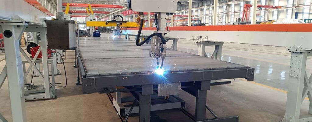
Прежде чем выбирать сварочных промышленных роботов, производители должны выполнить структурированный обзор реальной заготовки.
1. Определите каждое соединение
Запишите тип соединения, длину шва, размер сварного шва, положение сварки, материал, толщину и требуемый внешний вид. Не предполагайте, что в швах аналогичного вида используется одна и та же процедура.
2. Измерьте реальные изменения производства
Осмотрите несколько заготовок, а не полагайтесь только на один чертеж или образец. Измерьте изменение зазора, выравнивание кромок, положение прихватки, движение шва и общее искажение.
3. Подтвердите доступ к факелу
Ознакомьтесь с полным конвертом факела по каждому шву. Включите сопло, кабель, зажимы, приспособления, соседние компоненты и запястье робота.
4. Выберите процесс сварки
Сопоставьте процесс с геометрией соединения, материалом, требованиями к проникновению, необходимостью осаждения, состоянием поверхности и критериями качества.
5. Определите стратегию приспособления
Определите, какие поверхности располагают деталь, где размещены зажимы, как контролируется искажение и как операторы загружают узел.
6. Решите, необходимо ли зондирование
Стабильные повторяющиеся суставы могут использовать программирование обучения и повторения. для переменных суставов может потребоваться сенсорное зондирование, лазерное отслеживание, трехмерное зрение или адаптивная коррекция пути.
7. Планируйте последовательность сварки
Подумайте, как тепло от одного шва влияет на следующий. чередуйте стороны, вращайте заготовку, разделяйте длинные швы или планируйте периоды охлаждения, когда это необходимо.
8. Подтвердить репрезентативными образцами
В пробной сварке должны использоваться детали, представляющие производство, а не специально подготовленные демонстрационные детали. В ходе испытания следует проверить точность пути, сплавление, проникновение, внешний вид, деформацию, циклический поток, доступность и управляемость оператора.
Полезный тест автоматизации не “Может ли робот сделать это движение?” Лучший вопрос “Может ли вся система надежно повторить этот сварной шов при нормальном производственном изменении?”
Заключение
Сварочные промышленные роботы могут обрабатывать стыковые соединения, нахлесточные соединения, Т-образные соединения, угловые соединения, краевые соединения, угловые сварные швы, канавочные сварные швы, изогнутые швы и многие сложные многопроходные конфигурации.
Ограничивающим фактором редко является название соединения. Реальные ограничения связаны с изменением шва, блокировкой доступа к горелке, неподходящими приспособлениями, неконтролируемым искажением, плохой подготовкой кромок и несоответствием между роботизированной системой и заготовкой.
Прямые, повторяющиеся соединения со стабильной посадкой обычно проще всего автоматизировать. изогнутые, глубокие, переменные или многоходовые соединения требуют более детального планирования процесса и могут извлечь выгоду из позиционеров, внешних осей, отслеживания швов или трехмерного зрения.
Самые сильные роботизированные сварочные проекты начинаются с анализа суставов, а не выбора робота. когда заготовка, приспособление, процесс, система движения и метод измерения разрабатываются вместе, сварка промышленных роботов может дать стабильные результаты в широком диапазоне промышленных сборок.
ЧАСТО ЗАДАВАЕМЫЕ ВОПРОСЫ
Могут ли сварочные промышленные роботы справиться с сты
Да. большинство систем могут сваривать стыковые соединения, когда расположение шва, зазор корня, подготовка края и доступ горелки являются согласованными. более толстые конструкции канавок могут потребовать нескольких проходов, позиционера, отслеживания шва или сварки с обеих сторон для поддержания проникновения и контроля искажений.
Подходят ли поясные соединения для роботизированной сварки?
Да. соединения на коленях обычно автоматизированы с помощью угловой или точечной сварки. Надежные результаты зависят от стабильного перекрытия, плотного контакта между листами, повторяемого положения кромок и контролируемого ввода тепла. переменные зазоры могут изменить проникновение, форму борта и фактическое расположение шва робота.
Могут ли сварка промышленных роботов сваривать Т-образные соединения?
Да. большинство систем могут сваривать стыковые соединения, когда расположение шва, зазор корня, подготовка края и доступ горелки являются согласованными. более толстые конструкции канавок могут потребовать нескольких проходов, позиционера, отслеживания шва или сварки с обеих сторон для поддержания проникновения и контроля искажений.
Требуются ли все роботизированные сварные соединения системы зрения?
Зрение не требуется для каждого стабильного, повторяющегося соединения. Это становится ценным, когда меняется расположение шва, детали имеют более широкие допуски, приспособления не могут устранить вариации или смесь продуктов часто меняется. Зрение может определить местонахождение шва, исправить путь и уменьшить переучивание.
Могут ли сварочные промышленные роботы обрабатывать сложные изогнутые
Сложные соединения могут быть автоматизированы, когда робот имеет достаточный вылет, свободу ориентации, чувствительность и доступ без столкновений. изогнутые швы, многопроходные канавки и пересекающиеся соединения часто требуют автономного планирования, внешних осей, позиционеров или трехмерного зрения, а не базовой обучающей и повторяющейся ячейки.