
Table of Contents
Introduction

A safety scanner is one of the most important protective devices used on automated guided vehicles, autonomous mobile equipment, robotic workstations, and other moving industrial systems. It continuously observes a defined area and sends a safety-related signal when a person or object enters a configured detection zone.
In an AGV application, the scanner does more than identify an obstacle. It helps the control system decide when the vehicle should continue at normal speed, reduce speed, stop, or remain stationary. The effectiveness of this protection depends on the scanner itself, but also on its mounting position, field configuration, vehicle speed, braking performance, load condition, floor environment, and safety-control architecture.
A scanner with a long detection range can still provide inadequate protection if its fields are configured incorrectly. At the same time, an excessively large field may create frequent unnecessary stops and make the automated system difficult to operate.
A reliable installation therefore requires a balance between protective performance and practical production flow.
This guide explains:
- How a safety scanner detects people and objects
- The difference between warning and protective fields
- How AGV speed and braking affect field size
- Why one fixed field is rarely suitable for every movement
- How scanner placement influences blind spots
- What causes false detections and unnecessary stops
- How to integrate the scanner with vehicle controls
- How to validate protection under real operating conditions
What Is a Safety Scanner?
A safety scanner is an electro-sensitive protective device that monitors a programmable two-dimensional area around industrial equipment.
Many industrial scanners use a rotating laser beam to measure the distance and direction of nearby objects. This measuring principle is related to lidar, which determines range by emitting light and measuring the returned signal.
A safety-rated scanner is different from a general navigation sensor. It is designed to perform a defined protective function and communicate with an appropriate safety-control system.
A typical unit contains:
- A laser emitter
- Rotating optical components
- A receiver
- Distance-processing electronics
- Configurable detection fields
- Safety outputs
- Diagnostic outputs
- Field-selection inputs
- Status indicators
- A protective housing and optical window
- Configuration and validation software
The scanner repeatedly checks whether an object has entered one of its programmed fields. Its outputs then communicate the result to a safety relay, safety controller, vehicle controller, or integrated drive system.
How Does a Safety Scanner Work?
The scanner sends laser pulses across its field of view. When the light reaches an object, part of the signal returns to the receiver.
By evaluating the return time and scanning angle, the device estimates where the object is located relative to the scanner.
The process occurs continuously while the scanner is active.
Area scanning
The rotating optical system checks many points across the surrounding area. These measurements create a two-dimensional detection plane.
The scanner does not normally identify whether the detected object is a person, pallet, wall, vehicle, machine, or tool. It detects that an object has entered a configured area.
Field comparison
The measured object positions are compared with stored field shapes.
A single scanner may contain several field sets for different travel directions, speeds, operating modes, and workstation conditions.
Output switching
When an object enters a warning field, the scanner may send a non-safety signal that causes the vehicle to slow down, activate an alarm, or prepare to stop.
When an object enters the protective field, the safety outputs change state and initiate the defined safety response.
Vehicle response
The safety controller receives the signal and commands a safe reaction.
Depending on the system design, the response may include:
- Controlled deceleration
- Drive torque removal
- Application of mechanical brakes
- Prevention of vehicle startup
- Inhibition of lifting or turning
- Shutdown of nearby automated equipment
- Activation of visual or audible warnings
The scanner detects the intrusion, but the complete system determines whether the hazard is controlled in time.
Warning Fields and Protective Fields
A safety scanner installation usually uses at least two types of monitored zones.
Warning field
The warning field is the outer detection area. It identifies an approaching object before that object reaches the protective field.
Entering the warning field may cause the AGV to:
- Reduce speed
- Sound an alarm
- Flash an indicator
- Change its route
- Prepare the braking system
- Inform the fleet-management system
- Wait for the route to clear
A warning field improves operational flow because the vehicle can respond gradually rather than stopping immediately.
However, the warning field is not normally the final protective layer. Its output and reaction may not perform the same safety function as the protective field.
Protective field
The protective field is the area in which detection initiates the safety-related stop response.
Its dimensions must account for the complete distance traveled between the moment an object is detected and the moment hazardous movement ends.
This includes:
- Scanner response time
- Safety-controller response time
- Communication delay
- Drive-system response
- Brake activation
- Actual braking distance
- Vehicle load
- Floor condition
- Measurement tolerance
- Installation tolerance
- Additional application-specific margins
A field that covers only the mechanical braking distance may be too small because the vehicle continues moving while the scanner, controller, and drive system process the stop request.
Detection contour
Some installations also use a reference contour or surrounding structure to confirm that the scanner remains correctly positioned.
If the scanner moves, becomes misaligned, or loses the expected reference surface, the system can detect the condition rather than continuing with an invalid protective field.
Safety Scanner Zone Comparison
| Zone or function | Typical purpose | Expected machine response | Main design consideration |
|---|---|---|---|
| Warning field | Early obstacle detection | Slow down, alert, or prepare to stop | Avoid excessive nuisance reactions |
| Protective field | Safety-related intrusion detection | Initiate the validated safe stop | Cover the complete stopping distance |
| Near-field protection | Detect objects close to the vehicle | Prevent startup or stop low-speed movement | Scanner mounting height and blind area |
| Directional field | Protect the current direction of travel | Apply the field facing vehicle movement | Reliable direction and steering inputs |
| Turning field | Cover the swept path during steering | Slow or stop before side contact | Vehicle body and load tail swing |
| Docking field | Protect low-speed station approach | Permit controlled approach while monitoring hazards | Fixed equipment must not mask people |
| Reference contour | Confirm scanner position or field validity | Stop or inhibit operation after deviation | Stable reference surfaces |
Why Stopping Distance Determines Field Size
The protective field must be large enough to stop hazardous movement before the vehicle reaches the detected person or object.
This makes stopping performance one of the most important inputs in safety scanner design.
A practical way to understand the required field depth is:
Protective field depth must cover the distance traveled during system response, the distance traveled during braking, and the additional allowances required by the application.
Response distance
Response distance is the distance the vehicle travels before braking begins.
It can include the time required for:
- Object detection
- Scanner output switching
- Safety-controller processing
- Network communication
- Drive-command processing
- Brake activation
Even a short response interval becomes significant when the AGV moves quickly.
Braking distance
Braking distance begins when deceleration takes effect and ends when hazardous movement stops.
It depends on:
- Vehicle speed
- Total moving mass
- Load distribution
- Brake condition
- Wheel condition
- Floor friction
- Route gradient
- Drive-control settings
- Mechanical wear
- Emergency-stop behavior
The unloaded AGV may stop sooner than the same vehicle carrying its maximum permitted load.
Additional allowances
The field may also require allowances for measurement uncertainty, scanner installation, reflective conditions, vehicle overhang, protruding loads, and changes in the surrounding environment.
The correct value should come from a documented risk assessment and validated stop testing rather than an estimate based only on scanner range.
Why Scanner Range Is Not the Same as Safe Stopping Range
A scanner specification may state that the device can detect objects over a substantial distance. That does not mean every point within that range is automatically suitable as a protective field.
The usable field depends on several conditions.
Detection capability
The device must reliably detect the target under the expected operating conditions.
Target size, surface properties, angle, contamination, and environmental conditions may influence detection.
Field geometry
The required zone may be long and narrow, wide and shallow, curved, or divided around fixed structures.
The scanner’s maximum range does not indicate whether it can create the exact field shape required by the vehicle.
Response performance
A long detection range provides no benefit if the safety system reacts too slowly or if the AGV braking distance has not been verified.
Mounting position
Part of the scanner range may be blocked by the vehicle frame, forks, lifting platform, bumper, load, or protective cover.
The effective monitored area can therefore be smaller than the theoretical scanning area.
Environmental stability
Dust, welding smoke, water droplets, reflective surfaces, floor contamination, and direct optical interference may affect operation.
The installation should be tested in the actual production environment.
Dynamic Field Switching
An AGV rarely operates under one unchanging condition. It may move forward, reverse, turn, dock, carry different loads, or travel at several speeds.
Using one large protective field for every condition can cause frequent stops. Using one small field can create inadequate protection at higher speeds.
Dynamic field switching allows the system to apply a field set that matches the current movement.
Speed-dependent fields
A low-speed field can be shorter because the AGV requires less distance to stop.
As speed increases, the controller selects a longer protective field and may also enlarge the warning zone.
The selected field must correspond to the actual speed state, not only the speed command.
Direction-dependent fields
When the AGV travels forward, the forward scanner field becomes active. When it reverses, the rear field must provide equivalent protection.
The system should prevent movement if field selection does not agree with the actual direction.
Steering-dependent fields
During a turn, the vehicle and its load occupy a curved swept path.
A straight forward field may not cover the outer corner, side overhang, rear swing, or trailer movement. Turning fields should extend into the areas that the complete vehicle will occupy.
Load-dependent fields
A long, wide, or overhanging load changes the AGV footprint.
The safety scanner field may need to cover the load rather than only the vehicle body. Different field sets can be selected according to the confirmed load type.
Docking fields
During final docking, the AGV may intentionally approach a fixed conveyor, rack, workstation, or transfer frame.
A normal forward protective field would detect this equipment and stop the vehicle too early. A docking field can permit a controlled approach while continuing to monitor the areas where a person could enter.
Docking-field design must not create an unmonitored path beside or between the AGV and station.
Scanner Placement and Mounting Height
Correct mounting determines what the scanner can actually see.
Front mounting
A front-mounted scanner monitors the direction of normal travel.
It should be positioned so that the vehicle frame, bumper, forks, and cables do not block the required protective field.
Rear mounting
A rear scanner protects reverse movement and can monitor the area behind the AGV when it leaves a station.
Reverse operation should not depend solely on the forward scanner.
Corner mounting
Scanners installed near vehicle corners can improve coverage around turns and side areas.
The design must still account for overlap, field selection, and possible gaps between scanners.
Low mounting
A low-mounted scanner may detect legs, pallets, and low obstacles effectively. It may also be more exposed to floor dust, debris, impact, water, and damage.
Very low placement can allow the vehicle structure or uneven floor conditions to interfere with the scanning plane.
Higher mounting
A higher position may protect the optical window and improve the field of view.
However, the scanning plane must still intersect objects that need to be detected. A narrow object or part of a person could pass beneath an incorrectly positioned plane.
Angled mounting
Tilting the scanner changes the monitored plane. This can help address ramps, lifting movement, or special vehicle geometry, but it can also create unexpected gaps.
Any non-horizontal arrangement should be reviewed through three-dimensional layout analysis and physical validation.
Blind Spots Around the Vehicle
A safety scanner cannot monitor through solid objects. Any part of the vehicle or load that blocks the scanning plane creates a shadowed area.
Common sources of blind spots include:
- Forks
- Lift platforms
- Towing structures
- Wheel covers
- Battery compartments
- Protective frames
- Bumpers
- Conveyors
- Cargo overhang
- Trailers
- Fixtures
- Cable supports
Blind spots are especially important close to the vehicle. A person or object may be too near the scanner to enter the main field correctly, or it may remain hidden behind a structural component.
Possible risk-reduction methods include:
- Installing additional scanners
- Adding safety bumpers
- Using contact edges
- Repositioning the scanner
- Redesigning the vehicle frame
- Applying side protection
- Preventing movement when a blind zone is accessible
- Restricting pedestrian access
- Using verified minimum-speed modes
No single sensor should be assumed to cover areas that its physical position prevents it from observing.
Safety Scanner Integration with AGVs
A safety scanner must be integrated with the vehicle’s safety-related control system rather than treated as a general obstacle sensor.
An AGV vehicle may combine navigation, drive control, safety sensing, lifting, towing, docking, and task communication. The protective response must remain reliable across all these operating modes.
Safety outputs
The scanner’s safety outputs communicate whether the protective field is clear or interrupted.
These outputs should connect to a system capable of initiating and monitoring the required safe state.
Field-selection inputs
The controller may select different fields according to speed, direction, steering angle, load status, or docking mode.
Field selection should be safety-related when an incorrect field could create a hazard.
Encoder or speed information
The protective field should correspond to actual vehicle movement.
A system that selects a short field while the AGV is moving faster than expected creates an unsafe mismatch.
Brake monitoring
The system may need to confirm that the braking function remains available and that commanded stopping performance is achieved.
Brake wear or changing floor conditions can increase stopping distance even when the scanner functions correctly.
Restart control
After an object leaves the field, the AGV should restart only according to the validated operating logic.
Automatic restart may be acceptable in some controlled mobile applications, while other conditions may require confirmation that the area is clear and the task remains valid.
Fault handling
Loss of scanner communication, invalid field selection, contaminated optics, internal faults, or inconsistent inputs should place the vehicle in a defined safe condition.
A diagnostic warning should not be allowed to continue indefinitely when it affects the protective function.
Safety Scanner vs Navigation Sensor
Safety and navigation sensors may use similar laser-measuring principles, but their roles are different.
| Evaluation factor | Safety scanner | Navigation sensor |
| Primary purpose | Protect people by monitoring defined fields | Locate the vehicle and map surroundings |
| Output function | Safety-related stop or control signal | Position and environmental data |
| Field configuration | Warning and protective zones | Map points, features, or localization references |
| Failure response | Must lead to a defined safe condition | May trigger route recovery or navigation fault |
| Integration priority | Machine safety system | Motion-planning and fleet-control system |
| Validation | Requires protective-function testing | Requires localization and route testing |
| Interchangeability | Cannot be replaced by a general sensor without verification | Not normally intended as the primary protective device |
One scanner may support more than one function only when its design, configuration, outputs, and validation permit those functions.
A general lidar used for mapping should not automatically be treated as a safety scanner.
Safety Scanner vs Other Protective Devices
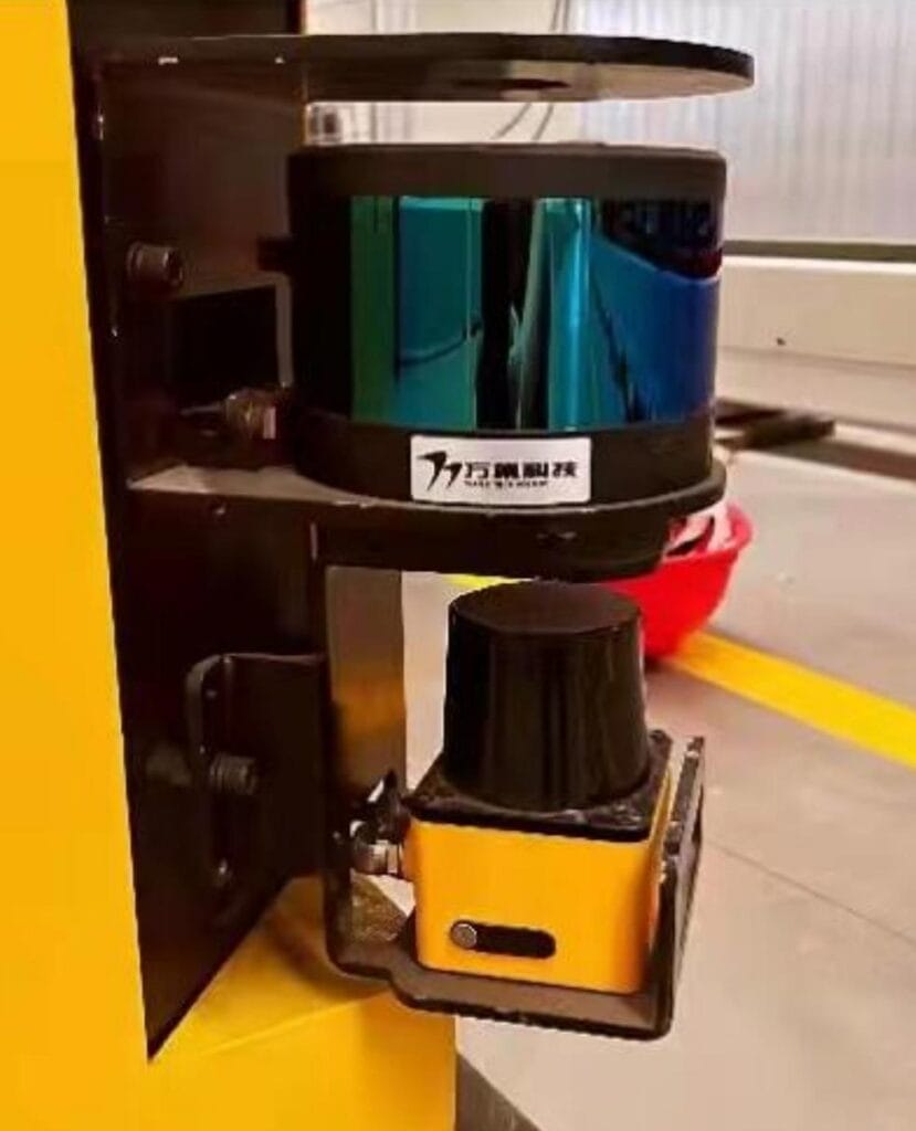
A safety scanner is valuable because it can monitor configurable open areas without requiring a physical barrier. However, other protective devices may be more suitable for certain hazards.
Safety light curtain
A light curtain creates a vertical detection plane.
It is often suitable for machine openings and controlled access points. It does not normally provide the same wide horizontal area coverage as a scanner.
Safety bumper
A bumper detects physical contact.
It is useful as a final protective layer near mobile equipment, particularly in areas that scanners cannot see. Because contact occurs before activation, stopping speed and impact force must remain controlled.
Safety edge
A safety edge is installed along a moving boundary, door, platform, or vehicle surface.
It protects a specific contact zone rather than monitoring a large area in advance.
Fixed guard
A fixed guard prevents access to a hazardous area.
It can provide strong separation where interaction is not required, but it is less flexible for shared AGV routes and material-transfer points.
Interlocked gate
An interlocked gate controls access to a hazardous zone and communicates its status to the safety system.
It is useful around robotic cells and fixed automated equipment but does not replace mobile-area detection.
Camera-based protection
Safety-rated vision systems may monitor more complex areas or vertical volumes.
They require suitable visibility, configuration, environmental control, and application validation.
The strongest solution may combine several technologies rather than expecting one safety scanner to manage every risk.
Common Causes of False Stops
Frequent unnecessary stopping reduces production stability and may encourage operators to distrust or bypass the protective system.
False stops should be investigated, not simply corrected by shrinking the field.
Dust and contamination
Dust, smoke, oil mist, water droplets, and debris can interfere with the optical window or appear within the monitored plane.
Regular cleaning and a suitable mounting location can reduce the problem.
Fixed equipment inside the field
Racks, columns, conveyors, guardrails, and stored materials may enter a field after a layout change.
The field should reflect the approved environment without creating gaps through which a person could approach.
Vehicle vibration
Loose mounting or excessive vibration can move the scanning plane and shift the relationship between the field and surrounding objects.
The mounting bracket should be rigid and regularly inspected.
Reflective surfaces
Highly reflective or unusual surfaces can affect optical behavior.
The application should be tested using the actual materials, angles, lighting, and distances found in production.
Incorrect field switching
A turning or docking field may fail to activate at the correct time, causing the scanner to detect nearby equipment.
The system logs should be reviewed to confirm the active field and the inputs that selected it.
Moving vehicle parts
Forks, lifting platforms, covers, and attachments may enter the scanning plane during operation.
Field logic should account for every permitted vehicle configuration.
Poor route clearance
A warning or protective field may overlap normal pedestrian areas, nearby machines, or adjacent AGV routes.
The correct response may require route redesign rather than reducing the field below the required stopping distance.
Common Dangerous Configuration Errors
Some configuration errors do not create frequent stops. Instead, they create areas where the vehicle may continue moving without adequate detection.
Field too short
A field based on estimated rather than measured stopping distance may not provide enough room under maximum load or unfavorable floor conditions.
Field too narrow
A narrow forward field may fail to cover the vehicle corners, steering movement, side overhang, or load width.
Missing rear protection
An AGV that occasionally reverses still requires protection for reverse movement.
Unprotected side movement
Vehicles capable of lateral travel or rotation need protection in the actual movement direction.
Incorrect field selected
A low-speed docking field must not remain active after the AGV accelerates.
Scanner blocked by the load
A pallet, fixture, or large component can obstruct the scanner after loading.
The field should be evaluated in every load condition.
Unverified software change
Changing scanner fields, vehicle speed, braking parameters, or route geometry can invalidate the original safety assessment.
Modified systems should be reviewed and tested before returning to normal operation.
Designing Safety Fields for Turns
Turning creates a more complex hazard zone than straight travel.
The front of the vehicle follows one curve, while the rear, sides, load, and trailers may follow different paths.
Outer swing
The outer corner of the vehicle may move beyond the forward field.
This is common when the scanner is mounted near the center rather than the leading outside corner.
Inner path
The inner side may move closer to a rack, machine, or pedestrian than expected.
A field designed only around the outer radius may miss this area.
Load overhang
Long workpieces can swing beyond the AGV body during steering.
The field should follow the load envelope, not only the chassis.
Trailer tracking
A towing vehicle and trailer do not follow the same curve.
The trailer may cut inside the AGV path, while its rear section may swing outward. Additional sensors or route controls may be necessary.
Rotation in place
An omnidirectional or steerable vehicle may rotate without moving forward.
Protection should cover the full rotational envelope during this movement.
A practical field design begins with a swept-path model and is then verified using physical tests at representative speeds and loads.
Docking Without Creating an Unprotected Zone
Docking is challenging because the AGV must intentionally approach a fixed object that the scanner would normally treat as an obstacle.
A carefully configured docking field can allow this movement while protecting the spaces around the vehicle.
Controlled approach speed
The final approach should use a verified low speed that matches the reduced protective field.
Station confirmation
The system should confirm that the AGV is approaching an approved docking station rather than applying the docking field anywhere along the route.
Side-entry protection
The field should continue monitoring the areas where a person could enter between the AGV and station.
Position verification
Docking-field selection may depend on route position, station communication, local markers, or other verified conditions.
Load-transfer interlocks
Conveyors, lift platforms, clamps, or towing devices should move only after the AGV position and safety conditions are confirmed.
Exit sequence
The normal travel field should become active before the AGV accelerates away from the station.
The broader reliability of an autonomous guided vehicle depends on the interaction of navigation, docking, braking, safety sensing, load handling, and fault recovery rather than on one component alone.
Environmental Conditions That Affect Performance
A safety scanner should be selected and installed according to the real operating environment.
Dust
Dust can accumulate on the optical window or remain suspended in the scanning plane.
Cleaning intervals should reflect actual contamination levels.
Welding smoke
Smoke and airborne particles may affect optical detection near welding operations.
Scanner placement, extraction, airflow, and protective covers should be evaluated together.
Water and condensation
Water droplets, cleaning spray, condensation, and wet floors can create unwanted detections or reduce visibility.
The scanner enclosure and installation should suit the environment.
Temperature
Extreme or changing temperatures may affect electronic equipment and create condensation.
The permitted operating range and warm-up requirements should be considered.
Vibration and shock
Mobile vehicles experience floor joints, ramps, impacts, and drive vibration.
The mounting system must preserve scanner alignment under normal movement.
Lighting and optical interference
Strong light sources or other optical devices may influence some installations.
The scanner manufacturer’s installation guidance should be followed and the finished system should be tested in normal operating conditions.
Floor reflections
The scanning plane may intersect reflective floor surfaces, ramps, metal plates, or changes in floor level.
A small mounting-angle error can cause the scanner to detect the floor unexpectedly.
Inspection and Maintenance
A safety scanner should remain part of the preventive-maintenance and safety-validation program throughout the equipment lifecycle.
Optical window inspection
Check for dust, scratches, oil, moisture, paint, welding spatter, and physical damage.
Cleaning should use materials and methods suitable for the optical surface.
Mounting inspection
Confirm that brackets, fasteners, guards, and alignment features remain secure.
A scanner can function electrically while its physical position no longer matches the validated field.
Field test
Use an appropriate test object and documented procedure to verify detection throughout the required protective area.
Testing only the center of the field may miss gaps near edges or blocked zones.
Stop test
Measure the vehicle’s actual stopping performance under representative conditions.
The test should include relevant speeds, loads, directions, routes, and floor conditions.
Field-switching test
Confirm that the correct field becomes active for forward travel, reverse travel, turns, docking, and load states.
Fault-response test
Verify that scanner faults, disconnected signals, invalid inputs, and controller faults produce the intended safe response.
Change management
Record changes to:
- Scanner configuration
- AGV speed
- Brake settings
- Vehicle structure
- Loads
- Routes
- Docking stations
- Floor conditions
- Safety software
- Surrounding equipment
Any change that affects stopping performance or detection coverage may require revalidation.
How to Select a Safety Scanner
A structured selection process helps match the device to the application.
Step 1: Define the hazardous movement
Identify the vehicle directions, speeds, steering modes, load-handling functions, and areas where people may approach.
Step 2: Determine the required field geometry
Measure the vehicle width, load envelope, turning path, reverse path, side movement, and docking conditions.
Step 3: Verify stopping performance
Use representative loads, speeds, brake conditions, gradients, and floor surfaces.
Do not rely only on the drive-system setting.
Step 4: Review the scanning range
Confirm that the scanner can cover the required field with suitable detection capability and installation allowance.
Step 5: Select the field-set capacity
Determine how many fields are required for speed levels, directions, turns, loads, stations, and operating modes.
Step 6: Evaluate mounting locations
Check field visibility, blind spots, physical protection, maintenance access, vibration, and contamination.
Step 7: Define safety integration
Specify the safety outputs, controller, drive response, field-selection logic, restart behavior, diagnostics, and fault state.
Step 8: Review the environment
Consider smoke, dust, reflective material, temperature, cleaning processes, water, floor changes, and optical interference.
Step 9: Validate the complete system
Test the finished vehicle rather than the scanner alone.
Step 10: Establish ongoing inspection
Create procedures for cleaning, field testing, stopping tests, configuration control, and maintenance records.
Validation Checklist
A practical validation should confirm that:
- The protective field covers the complete stopping requirement
- The warning field provides useful early response
- Forward and reverse protection work correctly
- Turning fields cover the full swept path
- Loads do not block the scanner
- Docking mode does not create an accessible gap
- The AGV stops under maximum representative load
- Field selection matches actual speed and direction
- Scanner faults cause the required response
- Blind spots have additional protection
- Environmental conditions do not cause unreliable detection
- Restart behavior matches the approved operating sequence
- Configuration files and test results are documented
Validation should involve the complete AGV, load, route, controller, brakes, scanner, and surrounding equipment.
Conclusion
A safety scanner helps AGVs and mobile industrial systems detect approaching people and objects before contact occurs. Its effectiveness depends on much more than nominal detection range.
Protective field depth must reflect the complete stopping process, including sensor response, control processing, brake activation, vehicle speed, load, floor conditions, and application allowances. Field width must cover steering movement, load overhang, side areas, and the complete swept path.
Dynamic field switching can improve both protection and production flow by matching the detection zone to speed, direction, turning, docking, and load conditions. However, the field-selection logic must remain consistent with actual vehicle movement.
Scanner mounting, blind spots, contamination, reflective surfaces, route layout, and software changes can all affect protection. These factors must be reviewed during design and checked throughout the system lifecycle.
The strongest safety scanner installation is not the one with the largest possible field. It is the system with correctly calculated zones, verified stopping performance, reliable control integration, documented testing, and practical protection across every operating mode.
FAQ
What does a safety scanner do on an AGV?
A safety scanner monitors programmable areas around the AGV and detects people or objects entering those zones. A warning field may reduce vehicle speed, while a protective field initiates the validated safety stop through the safety controller and drive system.
How large should a safety scanner protective field be?
The field must cover the distance traveled during scanner and controller response, brake activation, and actual deceleration. It should also include allowances for load, floor condition, gradient, measurement tolerance, vehicle overhang, and installation variation.
Can one safety scanner protect an entire AGV?
It depends on vehicle shape, travel directions, loads, lifting structures, and scanner placement. One unit may leave blind spots behind forks, platforms, frames, or cargo. Additional scanners, bumpers, safety edges, or access controls may be needed for complete protection.
Why does a safety scanner cause frequent AGV stops?
Common causes include dust, misalignment, nearby equipment, incorrect field switching, reflective surfaces, vehicle vibration, blocked scanning planes, or fields extending into normal traffic areas. The cause should be corrected without reducing the protective zone below the safe requirement.
Is a navigation lidar the same as a safety scanner?
No. A navigation lidar supplies environmental data for localization and route planning, while a safety scanner performs a validated protective function with safety-related outputs and defined failure behavior. A general navigation sensor should not replace safety equipment without proper assessment.