
Оглавление
Введение

Сканер безопасности является одним из наиболее важных защитных устройств, используемых на автоматизированных управляемых транспортных средствах, автономном мобильном оборудовании, роботизированных рабочих станциях и других движущихся промышленных системах. Он постоянно наблюдает за определенной областью и посылает сигнал, связанный с безопасностью, когда человек или объект входит в настроенную зону обнаружения.
В приложении AGV сканер делает больше, чем просто выявляет препятствие. это помогает системе управления решить, когда автомобиль должен продолжать движение на нормальной скорости, снизить скорость, остановиться или оставаться неподвижным. эффективность этой защиты зависит от самого сканера, а также от его монтажного положения, конфигурации поля, скорости автомобиля, эффективности торможения, состояния нагрузки, напольной среды и архитектуры управления безопасностью.
Сканер с большим диапазоном обнаружения все еще может обеспечить неадекватную защиту, если его поля настроены неправильно. в то же время чрезмерно большое поле может создавать частые ненужные остановки и затруднять работу автоматизированной системы.
Поэтому надежная установка требует баланса между защитными характеристиками и практическим производственным потоком.
В этом руководстве поясняется:
- Как сканер безопасности обнаруживает людей и предметы
- Разница между предупреждающими и защитными полями
- Как скорость и торможение AGV влияют на размер поля
- Почему одно фиксированное поле редко подходит для каждого движения
- Как размещение сканера влияет на слепые зоны
- Что вызывает ложные обнаружения и ненужные остановки
- Как интегрировать сканер с органами управления автомобилем
- Как проверить защиту в реальных условиях эксплуатации
Что такое сканер безопасности?
Сканер безопасности - это электрочувствительное защитное устройство, которое контролирует программируемую двумерную область вокруг промышленного оборудования.
Многие промышленные сканеры используют вращающийся лазерный луч для измерения расстояния и направления близлежащих объектов. с этим принципом измерения связано лидар, который определяет дальность путем излучения света и измерения возвращаемого сигнала.
Сканер с рейтингом безопасности отличается от общего навигационного датчика. Он предназначен для выполнения определенной защитной функции и связи с соответствующей системой управления безопасностью.
Типичный блок содержит
- Лазерный излучатель
- Вращающиеся оптические компоненты
- Приемник
- Дистанционная электроника
- Настраиваемые поля обнаружения
- Выходы безопасности
- Диагностические выходы
- Входы выбора поля
- Показатели состояния
- Защитный корпус и оптическое окно
- Программное обеспечение для настройки и проверки
Сканер неоднократно проверяет, вошел ли объект в одно из своих запрограммированных полей. Затем его выходы передают результат реле безопасности, контроллеру безопасности, контроллеру транспортного средства или интегрированной системе привода.
Как работает сканер безопасности?
Сканер посылает лазерные импульсы по полю своего зрения Когда свет достигает объекта, часть сигнала возвращается в приемник.
Оценива врем возврата и угол сканировани, устройство оценивает, где расположен объект относительно сканера.
Процесс происходит непрерывно, пока сканер активен.
Сканирование области
Вращающаяся оптическая система проверяет многие точки по всей окружающей области. эти измерения создают двумерную плоскость обнаружения.
Сканер обычно не определяет, является ли обнаруженный объект человеком, поддоном, стеной, транспортным средством, машиной или инструментом. Он обнаруживает, что объект вошел в настроенную область.
Сравнение полей
Измеренные положения объектов сравниваются с сохраненными формами полей.
Один сканер может содержать несколько наборов полей для различных направлений движения, скоростей, режимов работы и условий рабочего места.
Переключение выходов
Когда объект попадает в поле предупреждения, сканер может отправить сигнал отсутствия безопасности, который заставляет транспортное средство замедлиться, активировать сигнал тревоги или подготовиться к остановке.
Когда объект входит в защитное поле, выходные данные безопасности меняют состояние и инициируют определенную реакцию безопасности.
Реакция автомобиля
Контроллер безопасности принимает сигнал и дает команду на безопасную реакцию.
В зависимости от конструкции системы ответ может включать в себя
- Контролируемое замедление
- Удаление крутящего момента привода
- Применение механических тормозов
- Предотвращение запуска автомобиля
- Торможение подъема или поворота
- Отключение близлежащего автоматизированного оборудования
- Активация визуальных или звуковых предупреждений
Сканер обнаруживает вторжение, но вся система определяет, контролируется ли опасность вовремя.
Поля предупреждения и защитные поля
В установке сканера безопасности обычно используются как минимум два типа контролируемых зон.
Поле предупреждения
Поле предупреждения - это внешняя область обнаружения. Оно идентифицирует приближающийся объект до того, как этот объект достигнет защитного поля.
Вход в поле предупреждения может привести к тому, что AGV будет:
- Уменьшить скорость
- Подайте сигнал тревоги
- Просвечивайте индикатор
- Изменить свой маршрут
- Подготовьте тормозную систему
- Информировать систему управления автопарком
- Подождите, пока маршрут расчистится
Поле предупреждения улучшает эксплуатационный поток, поскольку транспортное средство может реагировать постепенно, а не останавливаться немедленно.
Однако поле предупреждения обычно не является конечным защитным слоем. Его выход и реакция могут не выполнять ту же функцию безопасности, что и защитное поле.
Защитное поле
Защитное поле - это область, в которой обнаружение инициирует реакцию остановки, связанную с безопасностью.
Его размеры должны учитывать полное расстояние, пройденное между моментом обнаружения объекта и моментом окончания опасного движения.
Сюда входят:
- Время отклика сканера
- Время срабатывания контроллера безопасности
- Задержка связи
- Реакция приводной системы
- Активация тормозов
- Фактический тормозной путь
- Нагрузка автомобиля
- Состояние пола
- Допуск измерения
- Допуск установки
- Дополнительные поля для конкретного приложения
Поле, которое охватывает только механический тормозной путь, может быть слишком малым, поскольку транспортное средство продолжает движение, пока сканер, контроллер и система привода обрабатывают запрос на остановку.
Контур обнаружения
Некоторые установки также используют эталонный контур или окружающую конструкцию для подтверждения правильного расположения сканера.
Если сканер движется, смещается или теряет ожидаемую опорную поверхность, система может обнаружить состояние, а не продолжать использовать недопустимое защитное поле.
Сравнение зон сканера безопасности
| Зона или функция | Типичная цель | Ожидаемый отклик машины | Основное внимание при проектировании |
|---|---|---|---|
| Поле предупреждения | Раннее обнаружение препятствий | Замедлитесь, насторожьтесь или приготовьтесь остановиться | Избегайте чрезмерных неприятных реакций |
| Защитное поле | Обнаружение вторжений, связанных с безопасностью | Начните проверенную безопасную остановку | Преодолейте полный тормозной путь |
| Защита ближнего поля | Обнаруживать объекты, находящиеся рядом с транспортным средством | Предотвратите запуск или остановите движение на низкой скорости | Высота монтажа сканера и глухая зона |
| Направленное поле | Защитите текущее направление движения | Примените поле, обращенное к движению автомобиля | Надежное направление и рулевое управление |
| Поворотное поле | Прикрывайте стреловидный путь во время рулевого управления | Замедленнее или остановитесь перед боковым контактом | Кузов автомобиля и поворот грузового оперения |
| Стыковочное поле | Защитите подход к низкоскоростной станции | Разрешить контролируемый заход на посадку при мониторинге опасностей | Фиксированное оборудование не должно маскировать людей |
| Эталонный контур | Подтвердите положение сканера или достоверность поля | Остановить или запретить работу после отклонения | Стабильные опорные поверхности |
Почему расстояние остановки определяет размер поля
Защитное поле должно быть достаточно большим, чтобы остановить опасное движение до того, как транспортное средство достигнет обнаруженного человека или объекта.
Это делает эффективность остановки одним из наиболее важных факторов в конструкции сканера безопасности.
Практический способ понять требуемую глубину поля заключается в
Глубина защитного поля должна охватывать расстояние, пройденное во время срабатывания системы, расстояние, пройденное во время торможения, и дополнительные припуски, требуемые приложением.
Расстояние ответа
Расстояние отклика - это расстояние, которое транспортное средство преодолевает до начала торможения.
В него можно включить время, необходимое для
- Обнаружение объектов
- Переключение выхода сканера
- Обработка контроллера безопасности
- Сетевая связь
- Обработка приводных команд
- Активация тормозов
Даже короткий интервал отклика становится значительным, когда AGV быстро движется.
Тормозной путь
Тормозной путь начинается, когда замедление вступает в силу, и заканчивается, когда опасное движение прекращается.
Это зависит от:
- Скорость автомобиля
- Общая движущаяся масса
- Распределение нагрузки
- Состояние тормозов
- Состояние колеса
- Фрикционное напольное
- Градиент маршрута
- Настройки управления приводом
- Механический износ
- Поведение аварийной остановки
Разгруженный AGV может остановиться раньше, чем то же транспортное средство, несущее максимально разрешенную нагрузку.
Дополнительные надбавки
Поле также может потребовать учета неопределенности измерений, установки сканера, условий отражения, свеса транспортного средства, выступающих нагрузок и изменений окружающей среды.
Правильное значение должно быть получено на основе документированной оценки риска и проверенного стоп-тестирования, а не оценки, основанной только на диапазоне сканирования.
Почему диапазон сканирования не такой же, как безопасный диапазон остановки
Спецификация сканера может указывать, что устройство может обнаруживать объекты на значительном расстоянии. Это не означает, что каждая точка в этом диапазоне автоматически подходит в качестве защитного поля.
Полезное поле зависит от нескольких условий.
Возможность обнаружения
Устройство должно надежно обнаруживать цель в ожидаемых условиях эксплуатации.
На обнаружение могут влиять целевой размер, свойства поверхности, угол, загрязнение и условия окружающей среды.
Геометрия поля
Требуемая зона может быть длинной и узкой, широкой и неглубокой, изогнутой или разделенной вокруг неподвижных конструкций.
Максимальный запас хода сканера не говорит о том, сможет ли он создать точную форму поля, необходимую транспортному средству.
Производительность ответа
Длительный диапазон обнаружения не дает никакой пользы, если система безопасности реагирует слишком медленно или если тормозной путь AGV не проверен.
Положение крепления
Часть диапазона сканеров может быть заблокирована рамой автомобиля, вилками, подъемной платформой, бампером, грузом или защитной крышкой.
Таким образом, эффективная контролируемая область может быть меньше теоретической области сканирования.
Экологическая стабильность
На работу могут повлиять пыль, сварочный дым, капли воды, отражающие поверхности, загрязнение пола и прямые оптические помехи.
Установка должна быть протестирована в реальных производственных условиях.
Динамическое переключение поля
AGV редко работает в одном неизменном состоянии. Он может двигаться вперед, задним ходом, поворачивать, стыковаться, нести разные грузы или двигаться с несколькими скоростями.
Использование одного большого защитного поля для каждого состояния может вызвать частые остановки. Использование одного небольшого поля может создать неадекватную защиту на более высоких скоростях.
Динамическое переключение полей позволяет системе применять набор полей, соответствующий текущему движению.
Поля, зависящие от скорости
Поле низкой скорости может быть короче, поскольку для остановки AGV требуется меньшее расстояние.
По мере увеличения скорости контроллер выбирает более длинное защитное поле, а также может увеличить зону предупреждения.
Выбранное поле должно соответствовать фактическому состоянию скорости, а не только команде скорости.
Поля, зависящие от направления
Когда AGV движется вперед, поле прямого сканера становится активным. когда оно поворачивает назад, заднее поле должно обеспечивать эквивалентную защиту.
Система должна предотвращать движение, если выбор поля не соответствует фактическому направлению.
Поля, зависящие от рулевого управления
Во время поворота транспортное средство и его груз занимают криволинейную стреловидную траекторию.
Прямое поле вперед может не закрывать внешний угол, боковой свес, задний поворот или движение прицепа. поля поворота должны простираться в области, которые займет все транспортное средство.
Зависимые от нагрузки поля
Длинная, широкая или нависающая нагрузка меняет площадь AGV.
Поле сканера безопасности может потребоваться для покрытия нагрузки, а не только кузова транспортного средства. различные наборы полей могут быть выбраны в соответствии с подтвержденным типом нагрузки.
Док-поля
Во время окончательной стыковки AGV может намеренно приблизиться к стационарному конвейеру, стойке, рабочей станции или передаточной раме.
Обычное переднее защитное поле обнаружит это оборудование и слишком рано остановит транспортное средство. Стыковочное поле может обеспечивать контролируемый заход на посадку, продолжая при этом контролировать области, куда человек может войти.
Конструкция стыковочного поля не должна создавать неконтролируемый путь рядом или между AGV и станцией.
Размещение сканера и высота монтажа
Правильное монтаж определяет, что сканер действительно может видеть.
Переднее крепление
Передний сканер отслеживает направление нормального движения.
Его следует расположить так, чтобы рама автомобиля, бампер, вилки, тросы не перекрывали требуемое защитное поле.
Задний монтаж
Задний сканер защищает обратное движение и может контролировать область за AGV, когда он покидает станцию.
Обратная работа не должна зависеть исключительно от прямого сканера.
Угловое крепление
Сканеры, установленные вблизи углов автомобиля, могут улучшить покрытие поворотов и боковых зон.
В конструкции по-прежнему должны учитываться перекрытие, выбор поля и возможные промежутки между сканерами.
Низкий монтаж
Низко расположенный сканер может эффективно обнаруживать ноги, поддоны и низкие препятствия. Он также может быть более подвержен воздействию пыли пола, мусора, ударов, воды и повреждений.
Очень низкое расположение может позволить конструкции транспортного средства или неравномерному полу мешать плоскости сканирования.
Более высокий монтаж
Более высокое положение может защитить оптическое окно и улучшить поле зрения.
Однако плоскость сканирования все равно должна пересекать объекты, которые необходимо обнаружить Узкий объект или часть человека могут пройти под неправильно расположенным самолетом.
Угловое крепление
Наклон сканера меняет контролируемую плоскость. Это может помочь решить проблему пандусов, подъемных движений или специальной геометрии автомобиля, но также может создать неожиданные зазоры.
Любое негоризонтальное расположение должно быть проверено посредством трехмерного анализа компоновки и физической проверки.
Слепые пятна вокруг автомобиля
Сканер безопасности не может отслеживать сквозь твердые предметы Любая часть транспортного средства или груз, блокирующий плоскость сканирования, создает затененную область.
К числу распространенных источников слепых зон относятся
- Вилки
- Лифтовые платформы
- Буксировочные сооружения
- Крышки колес
- Отсеки аккумулятора
- Защитные рамки
- Бамперы
- Конвейеры
- Грузовой свес
- Трейлеры
- Фиксации
- Подставки кабеля
Слепые зоны особенно важны вблизи транспортного средства. человек или объект может находиться слишком близко к сканеру, чтобы правильно войти в основное поле, или он может оставаться скрытым за структурным компонентом.
Возможные методы снижения риска включают в себя
- Установка дополнительных сканеров
- Добавление бамперов безопасности
- Использование контактных краев
- Перестановка сканера
- Перепроектирование рамы автомобиля
- Применение защиты стороны
- Предотвращение движения при доступности слепой зоны
- Ограничение доступа пешеходов
- Использование проверенных режимов минимальной скорости
Не следует предполагать, что ни один датчик охватывает области, за которыми его физическое положение не позволяет ему наблюдать.
Интеграция сканера безопасности с AGV
Сканер безопасности должен быть интегрирован с системой управления, связанной с безопасностью автомобиля, а не рассматриваться как общий датчик препятствий.
Ан Автомобиль AGV может сочетать навигацию, управление приводом, определение безопасности, подъем, буксировку, стыковку и связь с задачами. защитный отклик должен оставаться надежным на всех этих режимах работы.
Выходы безопасности
Выходы безопасности сканера сообщают, чистое или прерванное защитное поле.
Эти выходные данные должны подключаться к системе, способной инициировать и контролировать требуемое безопасное состояние.
Входы выбора поля
Контроллер может выбирать различные поля в зависимости от скорости, направления, угла поворота рулевого колеса, состояния нагрузки или режима стыковки.
Выбор поля должен быть связан с безопасностью, если неправильное поле может создать опасность.
Информация о кодере или скорости
Защитное поле должно соответствовать реальному движению транспортного средства.
Система, которая выбирает короткое поле, пока AGV движется быстрее, чем ожидалось, создает небезопасное несоответствие.
Мониторинг тормозов
Системе, возможно, потребуется подтвердить, что функция торможения остается доступной и что достигается заданная эффективность остановки.
Износ тормозов или изменение условий пола могут увеличить тормозной путь даже при правильной работе сканера.
Перезапустить контроль
После того, как объект покидает поле, AGV должен перезапускаться только в соответствии с проверенной операционной логикой.
Автоматический перезапуск может быть допустимым в некоторых контролируемых мобильных приложениях, в то время как другие условия могут потребовать подтверждения того, что область свободна и задача остается в силе.
Обработка неисправностей
Потеря связи со сканером, неправильный выбор поля, загрязненная оптика, внутренние неисправности или непоследовательные входные данные должны привести автомобиль в определенное безопасное состояние.
Нельзя допускать бесконечно длительного действия диагностического предупреждения, когда оно влияет на защитную функцию.
Сканер безопасности против навигационного датчика
Датчики безопасности и навигации могут использовать схожие принципы лазерного измерения, но их роли различны.
| Фактор оценки | Сканер безопасности | Навигационный датчик |
| Первичная цель | Защищайте людей, отслеживая определенные поля | Найдите автомобиль и составьте карту окрестностей |
| Выходная функция | Сигнал остановки или управления, связанный с безопасностью | Позиция и экологические данные |
| Конфигурация поля | Зоны предупреждения и защиты | Точки, функции или ссылки на локализацию карты |
| Отклик отказа | Должен привести к определенному безопасному состоянию | Может вызвать восстановление маршрута или навигационную неисправность |
| Приоритет интеграции | Система безопасности машины | Система планирования движения и управления автопарком |
| Валидация | Требуется проверка защитной функции | Требуется локализация и тестирование маршрута |
| Взаимозаменяемость | Не может быть заменен общим датчиком без проверки | Обычно не предназначено в качестве основного защитного устройства |
Один сканер может поддерживать более одной функции только в том случае, если его конструкция, конфигурация, выходные данные и проверка позволяют выполнять эти функции.
Общий лидар, используемый для картографирования, не следует автоматически рассматривать как сканер безопасности.
Сканер безопасности по сравнению с другими защитными устройствами
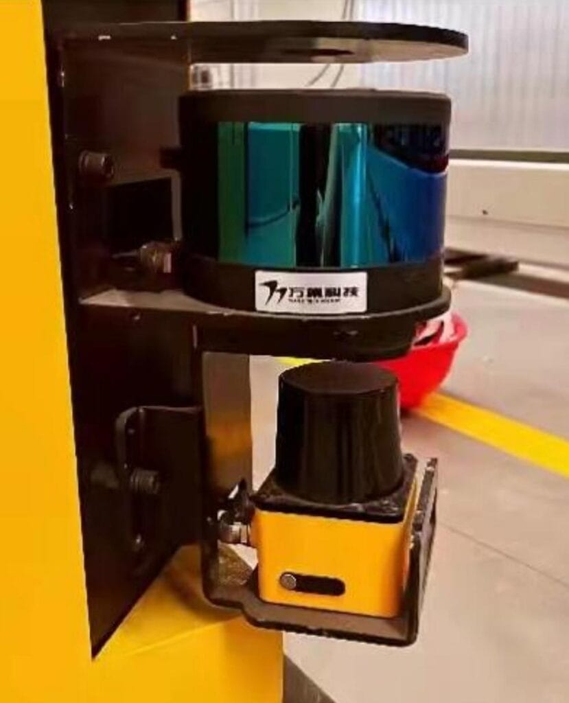
Сканер безопасности ценен, потому что он может контролировать конфигурируемые открытые области, не требуя физического барьера. Однако другие защитные устройства могут быть более подходящими для определенных опасностей.
Защитная световая завеса
Световая завеса создает вертикальную плоскость обнаружения.
Он часто подходит для машинных открытий и контролируемых точек доступа. обычно он не обеспечивает такой же широкий горизонтальный охват, как сканер.
Бампер безопасности
Бампер обнаруживает физический контакт.
Он полезен в качестве окончательного защитного слоя рядом с мобильным оборудованием, особенно в областях, которые сканеры не видят. Поскольку контакт происходит до активации, скорость остановки и сила удара должны оставаться контролируемыми.
Прекрас безопасности
По движущейся границе, двери, платформе, поверхности транспортного средства устанавливают предохранительную кромку.
Он защищает конкретную зону контакта, а не контролирует большую территорию заранее.
Фиксированная охрана
Фиксированное ограждение предотвращает доступ в опасную зону.
Он может обеспечить сильное разделение там, где взаимодействие не требуется, но он менее гибок для общих маршрутов AGV и точек передачи материала.
Сблокированные ворота
Сблокированные ворота контролируют доступ в опасную зону и сообщают о ее состоянии системе безопасности.
Он полезен в роботизированных камерах и стационарном автоматизированном оборудовании, но не заменяет обнаружение мобильных зон.
Защита на основе камеры
Системы технического зрения с уровнем безопасности могут отслеживать более сложные области или вертикальные объемы.
Они требуют подходящей видимости, конфигурации, контроля окружающей среды и проверки приложения.
Самое надежное решение может сочетать в себе несколько технологий, а не ожидать, что один сканер безопасности будет управлять каждым риском.
Общие причины ложных остановок
Частая ненужная остановка снижает стабильность производства и может побудить операторов не доверять защитной системе или обходить ее.
Ложные остановки следует исследовать, а не просто исправлять путем сокращения поля.
Пыль и загрязнение
Пыль, дым, масляный туман, капли воды и мусор могут мешать оптическому окну или появляться в контролируемой плоскости.
Регулярная очистка и подходящее место для монтажа могут уменьшить проблему.
Стационарное оборудование внутри поля
Стойки, колонны, конвейеры, ограждения и хранящиеся материалы могут попасть в поле после изменения планировки.
Поле должно отражать утвержденную среду, не создавая пробелов, через которые человек мог бы приблизиться.
Вибрация автомобиля
Свободное монтаж или чрезмерная вибрация могут сдвинуть плоскость сканирования и изменить соотношение между полем и окружающими объектами.
Монтажный кронштейн должен быть жестким и регулярно проверяться.
Отражающие поверхности
Высокоотражающие или необычные поверхности могут влиять на оптическое поведение.
Приложение следует тестировать с использованием реальных материалов, углов, освещения и расстояний, обнаруженных в производстве.
Неправильное переключение поля
Поворотное или стыковочное поле может не активироваться в нужное время, в результате чего сканер обнаружит близлежащее оборудование.
Системные журналы следует просмотреть для подтверждения активного поля и выбранных им входных данных.
Перемещение деталей автомобиля
Вилки, подъемные платформы, крышки и насадки могут попадать в плоскость сканирования во время работы.
Логика поля должна учитывать каждую разрешенную конфигурацию транспортного средства.
Плохое расчистка маршрута
Предупреждающее или защитное поле может перекрывать обычные пешеходные зоны, близлежащие машины или прилегающие маршруты AGV.
Правильный ответ может потребовать изменения дизайна маршрута, а не уменьшения поля ниже требуемого тормозного пути.
Общие опасные ошибки конфигурации
Некоторые ошибки конфигурации не создают частых остановок Вместо этого они создают области, где транспортное средство может продолжать движение без надлежащего обнаружения.
Поле слишком короткое
Поле, основанное на расчетном, а не измеренном тормозном пути, может не обеспечить достаточного пространства при максимальной нагрузке или неблагоприятных условиях пола.
Поле слишком узкое
Узкое переднее поле может не покрывать углы автомобиля, движение рулевого управления, боковой свес или ширину груза.
Отсутствие защиты задней части
AGV, который иногда поворачивает задним ходом, по-прежнему требует защиты для обратного движения.
Незащищенное боковое движение
Транспортные средства, способные перемещаться или вращаться вбок, нуждаются в защите в фактическом направлении движения.
Неправильное поле выбрано
Низкоскоростное стыковочное поле не должно оставаться активным после ускорения AGV.
Сканер заблокирован нагрузкой
Поддон, приспособление или крупный компонент могут заблокировать сканер после загрузки.
Поле следует оценивать в каждом состоянии нагрузки.
Непроверенное изменение программного обеспечения
Изменение полей сканера, скорости транспортного средства, параметров торможения или геометрии маршрута может сделать недействительной первоначальную оценку безопасности.
Модифицированные системы следует пересмотреть и протестировать перед возвращением к нормальной работе.
Проектирование полей безопасности для поворотов
Поворот создает более сложную зону опасности, чем прямой ход.
Передняя часть автомобиля следует одному повороту, а задняя часть, боковые стороны, груз и прицепы могут следовать разными путями.
Внешние качели
Внешний угол транспортного средства может перемещаться за пределы переднего поля.
Это часто происходит, когда сканер установлен рядом с центром, а не с передним внешним углом.
Внутренний путь
Внутренняя сторона может приблизиться к стойке, машине или пешеходу, чем ожидалось.
Поле, спроектированное только вокруг внешнего радиуса, может не попасть в эту область.
Нагрузочный свес
Длинные заготовки могут качаться за пределы корпуса AGV во время рулевого управления.
Поле должно соответствовать диапазону нагрузки, а не только шасси.
Отслеживание трейлера
Тягач и прицеп не следуют одной и той же кривой.
Прицеп может разрезаться внутри пути AGV, в то время как его задняя часть может раскачиваться наружу. могут потребоваться дополнительные датчики или средства управления маршрутом.
Вращение на месте
Всенаправленное или управляемое транспортное средство может вращаться без движения вперед.
Защита должна охватывать всю вращающуюся оболочку во время этого движения.
Практическое проектирование поля начинается с модели со стреловидной траекторией, а затем проверяется с помощью физических испытаний на репрезентативных скоростях и нагрузках.
Стыковка без создания незащищенной зоны
Стыковка является сложной задачей, поскольку AGV должен намеренно приближаться к фиксированному объекту, который сканер обычно рассматривает как препятствие.
Тщательно настроенное стыковочное поле может обеспечить такое движение, одновременно защищая пространство вокруг автомобиля.
Контролируемая скорость захода на посадку
При окончательном подходе следует использовать проверенную низкую скорость, соответствующую уменьшенному защитному полю.
Подтверждение станции
Система должна подтвердить, что AGV приближается к утвержденной док-станции, а не наносит стыковочное поле в любом месте маршрута.
Защита от бокового входа
Поле должно продолжать мониторинг районов, куда человек может войти между AGV и станцией.
Проверка позиции
Выбор стыковочного поля может зависеть от положения маршрута, связи станции, местных маркеров или других проверенных условий.
Передаточные блокировки нагрузки
Конвейеры, подъемные платформы, зажимы или буксирные устройства должны двигаться только после подтверждения положения AGV и условий безопасности.
Последовательность выхода
Обычное поле движения должно стать активным до того, как AGV ускорится от станции.
Более широкая надежность автономный управляемый автомобиль зависит от взаимодействия навигации, стыковки, торможения, определения безопасности, обработки нагрузки и устранения неисправностей, а не только от одного компонента.
Условия окружающей среды, влияющие на производительность
Сканер безопасности следует выбирать и устанавливать в соответствии с реальной рабочей средой.
Пыль
Пыль может накапливаться на оптическом окне или оставаться подвешенной в плоскости сканирования.
Интервалы очистки должны отражать фактические уровни загрязнения.
Сварочный дым
Дым и частицы, переносимые по воздуху, могут влиять на оптическое обнаружение вблизи сварочных операций.
Расположение, извлечение, поток воздуха и защитные крышки сканера следует оценивать вместе.
Вода и конденсация
Капли воды, распыление чистящих средств, конденсат и влажный пол могут создать нежелательные обнаружения или ухудшить видимость.
Корпус и установка сканера должны соответствовать окружающей среде.
Температура
Экстремальные или меняющиеся температуры могут повлиять на электронное оборудование и вызвать конденсацию.
Следует учитывать разрешенный рабочий диапазон и требования к прогреву.
Вибрация и удар
Мобильные автомобили испытывают стыки пола, пандусы, удары и вибрацию привода.
Система крепления должна сохранять выравнивание сканера при нормальном движении.
Освещение и оптические помехи
Сильные источники света или другие оптические устройства могут влиять на некоторые установки.
Следует соблюдать руководство по установке производителя сканера и испытывать готовую систему в нормальных условиях эксплуатации.
Отражения пола
Плоскость сканирования может пересекать отражающие поверхности пола, пандусы, металлические пластины или изменения уровня пола.
Небольшая ошибка монтажного угла может привести к тому, что сканер неожиданно обнаружит пол.
Инспекция и обслуживание
Сканер безопасности должен оставаться частью программы профилактического обслуживания и проверки безопасности на протяжении всего жизненного цикла оборудования.
Оптический осмотр окна
Проверьте наличие пыли, царапин, масла, влаги, краски, сварочных брызг и физических повреждений.
При очистке следует использовать материалы и методы, подходящие для оптической поверхности.
Монтажный осмотр
Подтвердите, что кронштейны, крепежные детали, ограждения и элементы выравнивания остаются надежными.
Сканер может работать электрически, пока его физическое положение больше не соответствует проверенному полю.
Полевое испытание
Используйте соответствующий объект испытаний и документированную процедуру для проверки обнаружения на всей необходимой защитной территории.
Тестирование только центра поля может не попасть в зазоры вблизи краев или в заблокированные зоны.
Остановить тест
Измеряют фактические показатели остановки транспортного средства в репрезентативных условиях.
Испытание должно включать соответствующие скорости, нагрузки, направления, маршруты и условия пола.
Тест на переключение поля
Подтвердите, что правильное поле становится активным для движения вперед, движения задним ходом, поворотов, стыковки и состояния загрузки.
Тест "отказ-реакция"
Убедитесь, что неисправности сканера, отключенные сигналы, недопустимые входы и неисправности контроллера вызывают предполагаемый безопасный ответ.
Управление изменениями
Запишите изменения в:
- Конфигурация сканера
- Скорость АГВ
- Настройки тормоза
- Конструкция автомобиля
- Грузы
- Маршруты
- Док-станции
- Условия пола
- Программное обеспечение безопасности
- Окружающее оборудование
Любое изменение, влияющее на остановку производительности или покрытие обнаружения, может потребовать повторной проверки.
Как выбрать сканер безопасности
Структурированный процесс выбора помогает сопоставить устройство с приложением.
Шаг 1: Определите опасное движение
Определите направления движения автомобиля, скорости, режимы рулевого управления, функции погрузочно-разгрузочных работ и зоны, к которым могут приближаться люди.
Шаг 2: Определите требуемую геометрию поля
Измеряют ширину транспортного средства, диапазон нагрузки, траекторию поворота, обратный путь, боковое перемещение и условия стыковки.
Шаг 3: Проверьте эффективность остановки
Используйте репрезентативные нагрузки, скорости, условия тормозов, уклоны и поверхности пола.
Не полагайтесь только на настройку приводной системы.
Шаг 4: Просмотрите диапазон сканирования
Подтвердите, что сканер может охватить необходимое поле с соответствующими возможностями обнаружения и допуском на установку.
Шаг 5: Выберите мощность набора полей
Определите, сколько полей требуется для уровней скорости, направлений, поворотов, нагрузок, станций и режимов работы.
Шаг 6: Оцените места установки
Проверьте видимость поля, слепые зоны, физическую защиту, доступ к техническому обслуживанию, вибрацию и загрязнение.
Шаг 7: Определите интеграцию безопасности
Укажите выходные данные безопасности, контроллер, реакцию привода, логику выбора поля, поведение перезапуска, диагностику и состояние неисправности.
Шаг 8: Просмотрите окружающую среду
Рассмотрим дым, пыль, отражающий материал, температуру, процессы очистки, воду, смену пола и оптические помехи.
Шаг 9: Проверьте всю систему
Испытайте готовый автомобиль, а не только сканер.
Шаг 10: Наладить постоянную проверку
Создавайте процедуры очистки, полевых испытаний, остановочных испытаний, контроля конфигурации и записей технического обслуживания.
Контрольный список проверки
Практическая проверка должна подтвердить, что
- Защитное поле покрывает полное требование остановки
- Поле предупреждения обеспечивает полезное раннее реагирование
- Правильно работают защита вперед и назад
- Поворотные поля покрывают всю пройденную траекторию
- Нагрузки не блокируют сканер
- Режим стыковки не создает доступного зазора
- AGV останавливается под максимальной репрезентативной нагрузкой
- Выбор поля соответствует фактической скорости и направлению
- Неисправности сканера вызывают требуемый отклик
- Слепые зоны имеют дополнительную защиту
- Условия окружающей среды не вызывают ненадежного обнаружения
- Поведение перезапуска соответствует утвержденной последовательности операций
- Файлы конфигурации и результаты тестирования документируются
Валидация должна включать в себя полный AGV, нагрузку, маршрут, контроллер, тормоза, сканер и окружающее оборудование.
Заключение
Сканер безопасности помогает AGV и мобильным промышленным системам обнаруживать приближающихся людей и объекты до того, как произойдет контакт. Его эффективность зависит от гораздо большего, чем номинальный диапазон обнаружения.
Глубина защитного поля должна отражать полный процесс остановки, включая реакцию датчика, обработку управления, активацию тормозов, скорость транспортного средства, нагрузку, состояние пола и припуски на применение. Ширина поля должна охватывать движение рулевого управления, свес нагрузки, боковые зоны и всю стреловидную траекторию.
Динамическое переключение поля может улучшить как защиту, так и производственный поток, согласовав зону обнаружения с условиями скорости, направления, поворота, стыковки и нагрузки. Однако логика выбора поля должна оставаться согласованной с фактическим движением транспортного средства.
Монтаж сканера, слепые зоны, загрязнение, отражающие поверхности, расположение маршрута и изменения программного обеспечения - все это может повлиять на защиту. эти факторы необходимо учитывать во время проектирования и проверять на протяжении всего жизненного цикла системы.
Самая сильная установка сканера безопасности не та, которая имеет максимально возможное поле. Это система с правильно рассчитанными зонами, проверенной производительностью остановки, надежной интеграцией управления, документированными испытаниями и практической защитой в каждом режиме работы.
ЧАСТО ЗАДАВАЕМЫЕ ВОПРОСЫ
Что делает сканер безопасности на AGV?
Сканер безопасности контролирует программируемые области вокруг AGV и обнаруживает людей или объекты, входящие в эти зоны. Поле предупреждения может снизить скорость транспортного средства, в то время как защитное поле инициирует проверенную предохранительную остановку через контроллер безопасности и систему привода.
Насколько большим должно быть защитное поле сканера безопасности?
Поле должно охватывать расстояние, пройденное во время срабатывания сканера и контроллера, срабатывания тормоза и фактического замедления. Оно также должно включать допуски на нагрузку, состояние пола, уклон, допуск на измерение, свес транспортного средства и изменение установки.
Может ли один сканер безопасности защитить весь AGV?
Это зависит от формы транспортного средства, направления движения, грузов, подъемных конструкций и размещения сканера. Один блок может оставить слепые зоны за вилами, платформами, рамами или грузом. Для полной защиты могут потребоваться дополнительные сканеры, бамперы, защитные кромки или средства контроля доступа.
Почему сканер безопасности вызывает частые остановки AGV?
Общие причины включают пыль, несоосность, близлежащее оборудование, неправильное переключение поля, отражающие поверхности, вибрацию транспортного средства, блокированные плоскости сканирования или поля, выходящие в обычные зоны движения. Причину следует исправить, не уменьшая защитную зону ниже безопасного требования.
Является ли навигационный лидар таким же, как сканер безопасности?
№ Навигационный лидар предоставляет данные об окружающей среде для локализации и планирования маршрута, в то время как сканер безопасности выполняет проверенную защитную функцию с выходами, связанными с безопасностью, и определенным поведением при сбоях. Общий навигационный датчик не должен заменять оборудование безопасности без надлежащей оценки.