
Mục lục
Giới thiệu
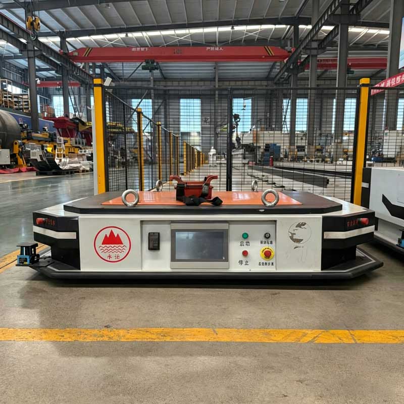
A laser guided AGV uses laser-based positioning to determine its location, follow planned routes, approach workstations, and transport materials through an industrial facility. Unlike a vehicle that follows a physical wire, magnetic strip, or painted line, it can navigate through a software-defined map without requiring a continuous guide path on the floor.
This flexibility makes laser navigation suitable for production environments where routes may need to connect storage areas, assembly stations, welding cells, loading points, conveyors, and inspection zones.
However, installing a laser scanner on a vehicle does not automatically create a reliable navigation system. The performance of a laser guided AGV depends on the interaction between reflector layout, scanner visibility, route geometry, localization software, wheel condition, floor quality, docking references, safety devices, and production controls.
A system may travel accurately through an open aisle yet struggle near a large load, a moving door, a reflective machine surface, or a workstation that blocks several positioning references. For this reason, navigation should be designed around the complete operating environment rather than only the vehicle specification.
Hướng dẫn này giải thích:
- How a laser guided AGV calculates its position
- The difference between reflector navigation and natural-feature localization
- Where reflectors should be installed
- Why line of sight affects navigation stability
- How route planning influences turning and docking
- What causes position drift or localization loss
- How navigation and safety scanners perform different jobs
- How to validate an AGV before full production
AGV hướng dẫn bằng laser là gì?
A laser guided AGV is an automated material-handling vehicle that uses laser measurements to localize itself within a mapped operating area.
The broader category of an xe dẫn hướng tự động includes vehicles that follow magnetic tape, embedded wires, optical lines, laser references, visual markers, or digitally mapped surroundings.
In a traditional reflector-based system, a rotating laser scanner mounted on the vehicle detects reflective targets installed around the facility. Because the coordinates of these reflectors are recorded in the navigation map, the controller can compare the measured angles and distances with the stored layout to estimate the vehicle’s position and heading.
Some modern systems use a laser scanner to recognize walls, columns, racks, and other permanent environmental features rather than relying mainly on artificial reflectors. Both methods use laser measurements, but their installation requirements and failure modes are different.
A complete laser guided AGV normally includes:
- A laser navigation scanner
- Reflectors or a natural-feature map
- Bộ điều khiển xe
- Navigation software
- Bộ mã hóa bánh xe
- Steering and drive system
- Máy quét an toàn
- Communication module
- Battery and charging system
- Cơ chế xử lý tải
- Position and docking sensors
- Fleet-management interface
The navigation scanner tells the vehicle where it is. The safety system determines whether it is permitted to continue moving.
Điều hướng Laser dựa trên gương phản xạ hoạt động như thế nào?
Reflector navigation is based on a known relationship between the AGV and fixed reference points.
Quét laser
The navigation scanner emits laser light while rotating across the surrounding area. Special reflectors return a strong signal to the scanner.
The controller records the direction and measured distance of each visible reflector.
Nhận dạng phản xạ
Each reflector does not necessarily need to transmit an individual electronic identity. The navigation software compares the observed pattern with the known coordinates stored in the map.
The shape and spacing of the visible reflector group help the controller determine which references it is seeing.
Tính toán vị trí
When enough reliable references are visible, the system calculates the vehicle’s position and orientation.
Wheel encoder data may support this calculation between scans, especially while the AGV is turning or when some reflectors are temporarily blocked.
Tuyến đường sau
The controller compares the calculated position with the planned route.
It then adjusts steering and drive commands to reduce the difference between the actual vehicle position and the required path.
Chỉnh sửa liên tục
The AGV repeats this process while moving. Laser measurements correct the gradual error that can accumulate from wheel slip, tire wear, uneven floors, and mechanical tolerances.
The system does not simply scan the reflectors once at startup. It continually updates its localization as the vehicle moves through the facility.
Điều hướng phản xạ so với Điều hướng tính năng tự nhiên
Both systems may be described as laser guided, but they use different environmental references.
Điều hướng dựa trên phản xạ
Reflector-based navigation uses purpose-installed targets with known coordinates.
Its main strengths are clear reference points, predictable signal behavior, and controlled map geometry. It can perform well in large open areas where permanent walls or racks do not provide enough distinctive features.
Its main limitation is the need to install, survey, protect, and maintain reflectors.
Điều hướng tính năng tự nhiên
Natural-feature localization uses existing structures such as walls, columns, fixed racks, and machinery to match live laser scans with a stored map.
It reduces the number of artificial markers required and can simplify route changes. However, the environment must contain enough stable and recognizable geometry.
An area with repeated identical racks, frequently moving equipment, or large open spaces may not provide a sufficiently distinctive scan pattern.
Điều hướng lai
A hybrid system uses natural features where they are reliable and adds reflectors or other references in difficult areas.
This can improve localization near loading stations, changing storage zones, long corridors, or open production areas.
The most suitable method depends on environmental stability, required docking performance, route flexibility, installation access, and maintenance capability.
So sánh phương pháp điều hướng
| Navigation method | Physical infrastructure | Route flexibility | Sức mạnh chính | Hạn chế chính |
|---|---|---|---|---|
| Reflector-based laser | Reflectors mounted around the facility | High after map updates | Stable, defined reference geometry | Requires clear reflector visibility |
| Natural-feature laser | Permanent environmental structures | Cao | Fewer artificial markers | Sensitive to major layout changes |
| Magnetic tape | Tape installed on the floor | Moderate | Simple route recognition | Floor path can wear or be obstructed |
| Magnetic spot | Discrete floor markers | Moderate | Less continuous floor infrastructure | Route changes require marker work |
| Embedded wire | Wire installed below the floor | Low | Stable fixed path | Difficult to modify after installation |
| Visual marker navigation | Printed or coded markers | Moderate to high | Clear local positioning references | Markers require visibility and maintenance |
| Điều hướng lai | Combination of references | Cao | Can strengthen difficult route sections | More complex system integration |
Các thành phần chính của AGV dẫn hướng bằng laser
Reliable navigation depends on more than one scanner.
Máy quét laser định vị
The navigation scanner observes reflectors or environmental contours and supplies measurement data for localization.
Its field of view should remain free from obstruction throughout normal operation.
Phản x
Reflectors provide high-contrast references for the scanner. They may be mounted on walls, columns, racks, support frames, or dedicated posts.
Their dimensions, height, orientation, and spacing should match the scanner and navigation-system requirements.
Bộ mã hóa bánh xe
Encoders measure wheel rotation and help estimate vehicle movement.
This form of motion estimation is useful between laser position updates, but it gradually accumulates error if used alone.
Cảm biến lái
The controller may need feedback about steering angle or wheel orientation.
Incorrect steering feedback can cause route-following errors even when localization remains accurate.
Bộ điều khiển xe
The controller calculates position, compares it with the route, and commands the drive and steering system.
It also exchanges information with load-handling equipment, safety controls, and fleet-management software.
Máy quét an toàn
A safety scanner monitors protective and warning fields around the vehicle.
It should not be confused with the navigation scanner. A general navigation sensor is not automatically suitable for performing a safety-related protective function.
Hệ thống truyền thông
The AGV communicates with dispatching software, workstations, doors, conveyors, lifts, chargers, and production systems.
Navigation may continue locally during a brief communication interruption, but task execution and traffic management require defined fault behavior.
Cơ chế xử lý tải
The vehicle may include a hydraulic lift, roller conveyor, fork structure, towing mechanism, or custom fixture.
This equipment can block the laser field or change the vehicle footprint, so it must be included in navigation and safety planning.
Vị trí phản xạ ảnh hưởng đến điều hướng như thế nào
Reflector layout is one of the most important design tasks in a traditional laser guided AGV project.
The objective is not simply to install as many reflectors as possible. The objective is to provide stable, recognizable reference geometry along every permitted route and operating mode.
Duy trì sự tách góc hữu ích
Reflectors should not appear as one narrow cluster from the vehicle’s viewpoint.
When references are distributed across different directions, the localization calculation has stronger geometric information.
A group of reflectors located almost in the same direction may provide less reliable positioning than a smaller group with wider angular separation.
Tránh các mẫu lặp đi lặp lại
Long rows of reflectors placed at identical intervals can create patterns that look similar from several positions.
A more distinctive layout helps the navigation system match observed references with the correct map location.
Che các ngã rẽ và giao lộ
A vehicle approaching a turn should see useful references before, during, and after steering.
Reflectors that are visible only on the straight aisle may disappear when the vehicle rotates.
Bảo vệ khu vực docking
Docking stations often require more consistent final positioning than ordinary route travel.
The reflector layout should provide clear references during the entire final approach rather than only at the station entrance.
Xem xét định hướng xe
A reflector that is visible when the AGV travels forward may be hidden when the vehicle reverses or rotates.
Every permitted direction should be reviewed.
Cung cấp sự chồng chéo giữa các khu vực
The vehicle should not move from one reflector group into another through a section where too few references are visible.
Overlapping visibility supports a smoother transition between mapped areas.
Chiều cao lắp đặt và đường ngắm
The navigation laser normally scans in a horizontal plane. Reflectors must intersect that plane and remain visible from the expected vehicle positions.
Chiều cao lắp đặt nhất quán
Reflectors should be installed at a controlled height relative to the scanner.
Large height variation can prevent the scanning plane from reaching the reflector, particularly on ramps or uneven floors.
Tắc nghẽn tải
A tall pallet, fixture, container, or workpiece can block reflectors that are visible when the AGV is unloaded.
The reflector study must include every representative load configuration.
Thiết bị cố định
Machine frames, conveyors, guardrails, columns, cabinets, and storage racks can create permanent shadows.
A reflector behind such equipment may be physically present but unavailable to the scanner.
Di chuyển vật cản
Forklifts, carts, operators, doors, cranes, and temporary material storage may block references intermittently.
A robust layout should tolerate limited temporary occlusion without immediately losing localization.
Kết cấu xe
Masts, lifting columns, forks, towing mechanisms, protective frames, and cables may obstruct the scanner as the vehicle turns or lifts.
Scanner placement should be reviewed using the complete vehicle model.
Độ dốc sàn
When an AGV travels up or down a slope, its scanning plane tilts relative to reflectors mounted on level walls.
Reflector dimensions and installation heights should accommodate the expected change, or another navigation strategy should be used in that section.
Hiểu phong bì bản địa hóa
A useful way to evaluate laser navigation is to define a localization envelope.
The localization envelope is the range of real operating conditions within which the AGV can still determine its position reliably.
It includes:
- Minimum number of useful visible references
- Reflector angular distribution
- Expected temporary blockage
- Vehicle direction
- Load dimensions
- Scanner mounting tolerance
- Floor slope
- Environmental contamination
- Route position
- Map accuracy
- Wheel slip
- Layout changes
This approach is more practical than testing localization only with an empty vehicle on a clear route.
A reliable laser guided AGV should remain localized during normal production variation, not only during an ideal demonstration.
Lập kế hoạch lộ trình cho AGV có hướng dẫn bằng laser
Laser navigation provides route flexibility, but the vehicle still obeys physical limits.
Chiều rộng lối đi
The route must accommodate the complete AGV, load, safety fields, steering error, and surrounding clearance.
The vehicle body alone does not define the required width.
Bán kính quay
The planned curve should match the steering geometry and wheel arrangement.
A route that forces continuous maximum steering can increase tire wear and reduce docking consistency.
Đường quét
During a turn, different parts of the vehicle and load follow different paths.
Long loads, towing devices, and trailers may move outside the path followed by the navigation reference point.
Giao lộ tuyến đường
Intersections require traffic rules and sufficient visibility.
The fleet-management system should control priority, reservation, waiting points, and safe separation between vehicles.
Các địa điểm dừng
Routine stopping positions should avoid blocking doors, crossings, workstations, emergency access, and other AGV routes.
Stopping at a location with weak laser visibility can also make restarting more difficult.
Du lịch một chiều và hai chiều
One-way routes simplify traffic control but may increase travel distance.
Two-way routes can use space efficiently but require enough passing clearance and stronger traffic-management logic.
Đường dốc và chuyển tiếp
Floor gradients affect traction, braking, scanning height, and load stability.
The route design should consider both navigation and mechanical performance.
Độ chính xác của Docking và Định vị cuối cùng
General route navigation and workstation docking are related but different tasks.
An AGV may travel accurately through an aisle yet still require additional references for precise load transfer.
Định vị phương pháp tiếp cận dựa trên laser
The laser map guides the vehicle toward the station and controls its approximate position and heading.
A strong reflector or feature layout near the station helps reduce approach error.
Cảm biến lắp ghép cục bộ
The final approach may use proximity sensors, laser distance sensors, cameras, markers, mechanical guides, or station references.
These devices can correct small differences that remain after general navigation.
Hướng dẫn cơ khí
Guide rails, tapered blocks, wheel guides, and locating cones can help establish the final physical relationship between the vehicle and workstation.
Mechanical guidance should correct limited error without creating repeated impact.
Căn chỉnh chiều cao
When transferring a pallet or carrier, horizontal position alone is insufficient.
The AGV lift, conveyor, or fork height must match the receiving station under representative load.
Điều khiển tiêu đề
A small angular error can create a large side mismatch at the end of a long pallet or fork.
Docking validation should measure both position and heading.
Truyền thông trạm
The AGV and workstation should confirm readiness before transfer begins.
A typical sequence may require confirmation of vehicle position, station availability, load presence, platform height, safety conditions, and transfer completion.
The Xe AGV should therefore be selected as a complete handling system rather than only as a mobile chassis.
Độ chính xác điều hướng so với Docking lặp lại
Navigation accuracy describes how closely the AGV estimates and follows its position within the map.
Docking repeatability describes how consistently the vehicle returns to the same physical relationship with a workstation.
These results are influenced by different factors.
Navigation performance depends heavily on:
- Map quality
- Laser reference visibility
- Localization algorithms
- Encoder feedback
- Steering control
- Route geometry
Docking repeatability also depends on:
- Station design
- Final approach speed
- Tình trạng sàn
- Tire wear
- Load distribution
- Mechanical clearance
- Local sensors
- Transfer forces
A system may report a stable map position while the physical vehicle shifts slightly because of wheel compression, mechanical play, or an uneven floor.
For automated transfer, the physical interface is the final measure of performance.
Máy quét an toàn và Máy quét điều hướng Sự khác biệt
A laser guided AGV may use more than one laser-based device, but those devices should not be assumed to perform the same role.
Máy quét điều hướng
The navigation scanner measures reflectors or environmental features to estimate vehicle position.
Its primary output supports route following and localization.
Máy quét an toàn
The safety scanner monitors warning and protective fields around the moving vehicle.
When a person or object enters a protective field, the safety system initiates the validated response.
Cảm biến phát hiện chướng ngại vật
Some vehicles also use general-purpose sensors to improve route planning, detect objects, or support docking.
These sensors may improve operation without being part of the safety-related control function.
Tại sao sự tách biệt lại quan trọng
A navigation system may continue calculating position while an obstacle is present. A safety system must respond according to the defined risk-control logic.
Likewise, a safety scanner can detect an object without knowing the AGV’s exact map location.
The integration should clearly define which device controls localization, production behavior, and personnel protection.
Bố cục thay đổi ảnh hưởng như thế nào đến điều hướng bằng laser
Laser routes are software-defined, but the surrounding environment remains part of the navigation system.
Phản xạ di chuyển hoặc bị hư hỏng
A reflector that is removed, rotated, covered, or replaced at the wrong position no longer matches the original map.
The AGV may ignore it, calculate a poorer position, or report a localization fault.
Máy móc mới
A new machine, rack, wall, or enclosure can block several references.
The route may require additional reflectors or a map update.
Lưu trữ tạm thời
Pallets and large components placed along an aisle can obstruct the scanner even when they do not physically block the AGV path.
Storage rules should protect both travel clearance and navigation visibility.
Thay đổi cửa hoặc vách ngăn
A moving door or new partition can alter natural-feature maps and block reflectors.
The system should be reviewed after building modifications.
Máy trạm được di dời
Changing a workstation position without updating navigation, docking, and traffic-control data can create repeated positioning errors.
Các loại tải mới
A taller or wider load may obstruct references or change the required safety fields.
Load changes should be included in formal system-change management.
Các vấn đề về điều hướng AGV được hướng dẫn bằng laser phổ biến
AGV mất khả năng bản địa hóa trong một đoạn tuyến
Likely causes include insufficient visible reflectors, poor reference geometry, environmental changes, load obstruction, or an inaccurate map.
Installing one additional reflector may not solve the problem if it appears in the same direction as the existing references.
Độ chính xác của vị trí giảm gần máy trạm
The station may block reflectors during the final approach. Nearby reflective surfaces or moving equipment may also change the scan environment.
The reference layout should be evaluated from the vehicle’s actual approach positions.
AGV đi theo một con đường hơi khác khi được tải
The load may change wheel compression, steering response, vehicle balance, or scanner visibility.
Testing only the unloaded vehicle can hide these effects.
Xe dao động quanh tuyến đường
Possible causes include aggressive steering corrections, incorrect controller tuning, wheel wear, mechanical clearance, route curvature, or inconsistent localization updates.
The navigation and motion-control data should be reviewed together.
Bản địa hóa không thành công trong một lượt
Reflectors visible on the straight route may disappear as the scanner rotates with the vehicle.
The turn needs reference coverage throughout the complete change in heading.
Lỗi dock tăng theo thời gian
Tire wear, steering play, loose sensors, moved reflectors, floor damage, fixture movement, or mechanical guide wear may gradually change the final position.
Repeated software offsets can hide the root cause rather than correct it.
Xuất hiện phát hiện phản xạ sai
Unplanned reflective surfaces may return strong laser signals.
The configuration should distinguish approved reflectors from environmental reflections, and the installation should be tested with actual machinery and materials.
Các yếu tố môi trường
Laser navigation must operate in the real production environment.
Bụi
Dust can cover scanner optics and reflectors, reducing signal quality.
Cleaning frequency should match the actual contamination level.
Khói hàn và các hạt trong không khí
Smoke, oil mist, steam, and suspended particles may affect the laser path or optical window.
Ventilation and scanner placement should be considered during layout design.
Bề mặt kim loại phản chiếu
Highly reflective equipment can create unexpected returns.
Testing should include the actual surface angles and vehicle positions.
Chiếu sáng
Laser systems are designed to operate under industrial lighting, but strong optical sources and unusual reflections should still be evaluated.
Nhiệt độ
Temperature changes can affect electronics, batteries, tires, hydraulic systems, and mechanical dimensions.
Condensation may also contaminate optical surfaces.
Rung
Floor joints, damaged surfaces, ramps, and vehicle impacts can change scanner alignment.
Mounting brackets should remain rigid under normal travel conditions.
Chất lượng sàn
Uneven floors affect wheel contact, vehicle heading, scanner height, docking accuracy, and load stability.
A navigation problem may therefore originate from the floor rather than from the laser system.
Quản lý đội tàu và kiểm soát giao thông
A laser guided AGV requires more than individual route-following capability when several vehicles share the same facility.
Phân bổ nhiệm vụ
The fleet system assigns transport requests according to vehicle availability, load capability, battery condition, position, and production priority.
Đặt chỗ tuyến đường
The system reserves route segments to prevent conflicting vehicle movements.
Reservations should consider vehicle length, loads, trailers, intersections, and stopping positions.
Kiểm soát tắc nghẽn
Sending every available AGV toward the same station can create queues and block surrounding routes.
Waiting points and task timing should be planned.
Quản lý pin
Charging tasks should be scheduled without removing too many vehicles from production at the same time.
The charging location also needs reliable navigation references and safe access.
Phục hồi lỗi
When one AGV stops, the fleet system should determine whether other vehicles can reroute, wait, or continue safely.
A vehicle fault should not create a chain of blocked routes without a recovery plan.
Truyền thông sản xuất
The AGV may exchange data with warehouse software, manufacturing systems, conveyors, doors, lifts, robots, and inspection stations.
The role of an xe dẫn đường tự động trong sản xuất thông minh is therefore broader than navigation alone; it must connect material movement with the production sequence.
Yêu cầu bảo trì
A laser guided AGV should be maintained as a complete navigation and motion system.
Quang học máy quét sạch
Dust, oil, fingerprints, moisture, and scratches can affect laser measurements.
Cleaning should use suitable materials and avoid damaging optical surfaces.
Kiểm tra phản xạ
Check reflector cleanliness, position, orientation, mounting security, and physical damage.
A reflector should not be moved casually during building or equipment maintenance.
Xác minh việc gắn máy quét
Loose brackets can shift the navigation reference frame.
The scanner may still operate while reporting a position that no longer corresponds correctly to the vehicle body.
Kiểm tra bánh xe và lốp xe
Wheel diameter, wear, pressure where applicable, and surface condition affect motion estimation and route following.
Uneven wear can create heading errors.
Kiểm tra các thành phần lái
Mechanical play, damaged bearings, loose linkages, and incorrect steering calibration can reduce path consistency.
Xem lại hiệu suất của bộ mã hóa
Encoder faults or incorrect scaling can cause the controller to estimate movement incorrectly between laser updates.
Xác nhận tính toàn vẹn của bản đồ
Navigation maps, reflector coordinates, workstation positions, routes, and software versions should be controlled.
Unauthorized changes can make troubleshooting difficult.
Kiểm tra docking
Regularly verify the physical transfer position under representative loads.
A successful empty-vehicle arrival does not prove that loaded transfer remains reliable.
Cách chọn AGV có hướng dẫn bằng laser
A structured selection process should begin with the transport task rather than the navigation technology alone.
Bước 1: Xác định tải
Record weight, dimensions, center of gravity, carrier design, loading method, and possible variation.
Bước 2: Lập bản đồ mọi tuyến đường
Identify aisle widths, turns, intersections, ramps, doors, stations, storage zones, and pedestrian areas.
Bước 3: Xem xét môi trường
Determine whether reflectors can be mounted with stable line of sight or whether natural-feature localization is more practical.
Bước 4: Xác định các yêu cầu lắp ghép
Establish the permitted position, heading, and height error at each transfer station.
Bước 5: Chọn cấu trúc xe
Choose a lifting, towing, conveyor, fork, under-ride, or customized load-handling configuration.
Bước 6: Đánh giá khả năng hiển thị điều hướng
Study reflector or feature availability with the vehicle loaded, unloaded, turning, docking, reversing, and lifting.
Bước 7: Xác định các chức năng an toàn
Plan warning fields, protective fields, emergency stops, bumpers, speed control, access zones, and restart behavior.
Bước 8: Lập kế hoạch truyền thông hệ thống
List the signals exchanged with workstations, fleet software, doors, lifts, conveyors, chargers, and production systems.
Bước 9: Xác định quyền sở hữu bảo trì
Assign responsibility for reflectors, maps, scanner cleaning, wheel condition, route changes, and validation records.
Bước 10: Kiểm tra sản xuất đại diện
The trial should include normal load variation, real operators, actual route traffic, different shifts, temporary obstructions, repeated docking, and fault recovery.
Danh sách kiểm tra vận hành và xác nhận
Before production release, verify that:
- Reflector or natural-feature coverage is sufficient along every route
- Reference geometry remains useful through turns
- Loads do not block the navigation scanner
- Forward and reverse movement remain localized
- The vehicle follows the planned swept path
- Docking position and heading meet transfer requirements
- Safety fields match speed, direction, steering, and load
- Actual stopping performance has been tested
- Communication faults produce controlled behavior
- Route intersections are managed correctly
- Charging navigation works reliably
- Temporary obstruction does not cause uncontrolled movement
- Scanner and reflector maintenance procedures are documented
- Software and map versions are controlled
- Layout changes trigger a formal review
- Recovery from localization loss is safe and understandable
Validation should be repeated after changes to routes, reflectors, vehicle speed, loads, docking stations, scanners, wheels, safety fields, or surrounding equipment.
Kết luận
A laser guided AGV can provide flexible, software-defined material transport without relying on a continuous floor guide. It can connect production stations, storage areas, conveyors, automated equipment, and loading points while supporting future route changes.
Reflector-based systems calculate position from fixed laser references, while natural-feature systems compare live scans with permanent environmental geometry. Hybrid approaches can strengthen areas where one method alone is not sufficiently reliable.
The success of the system depends on reference visibility, reflector geometry, map quality, scanner mounting, route design, steering control, wheel condition, docking equipment, safety integration, and change management.
The most important insight is that laser navigation is partly a property of the vehicle and partly a property of the facility. Moving a reflector, blocking a scan line, changing a load, or installing new equipment can influence navigation even when nothing on the AGV has changed.
A reliable laser guided AGV project therefore begins with a complete study of the load, vehicle, route, environment, workstation interfaces, and production controls. When these elements are designed and validated together, laser guidance can provide stable localization and adaptable material flow across a wide range of industrial operations.
Câu hỏi thường gặp
AGV dẫn hướng bằng laser là gì?
Một AGV dẫn hướng bằng laser sử dụng máy quét laser để xác định vị trí của nó và đi theo các tuyến đường được xác định bằng phần mềm. nó có thể phát hiện các gương phản xạ cố định với tọa độ đã biết hoặc so sánh các bức tường và cấu trúc xung quanh với bản đồ được lưu trữ. bộ điều khiển liên tục điều chỉnh chuyển động của xe bằng cách sử dụng dữ liệu laser và bộ mã hóa.
AGV dẫn hướng bằng laser có luôn cần gương phản xạ không?
Số Điều hướng laser truyền thống sử dụng gương phản xạ, trong khi bản địa hóa tính năng tự nhiên sử dụng tường, cột, giá đỡ và máy móc ổn định. Gương phản xạ vẫn hữu ích ở những khu vực mở, lặp đi lặp lại hoặc thay đổi nơi các đặc điểm môi trường không cung cấp đủ thông tin định vị đặc biệt.
AGV dẫn hướng bằng laser có độ chính xác như thế nào?
Hiệu suất phụ thuộc vào hình học phản xạ hoặc tính năng, khả năng hiển thị của máy quét, chất lượng bản đồ, tình trạng bánh xe, kiểm soát lái, chất lượng sàn, phân phối tải và thiết kế lắp ghép. độ chính xác của vị trí tuyến đường và độ lặp lại chuyển cuối cùng phải được kiểm tra riêng biệt trong điều kiện sản xuất đại diện.
Why does a laser guided AGV lose its position?
Localization loss may result from blocked or dirty reflectors, weak reference geometry, moved equipment, scanner contamination, load obstruction, map errors, floor slopes, wheel slip, or loose scanner mounting. The route section should be reviewed under the exact condition that causes the fault.
Is a navigation laser also a safety scanner?
Not necessarily. A navigation laser estimates the vehicle’s position, while a safety scanner monitors protective fields and initiates a validated safety response. The devices may use similar measuring principles, but their functions, outputs, fault behavior, and system validation are different.