
Оглавление
Введение
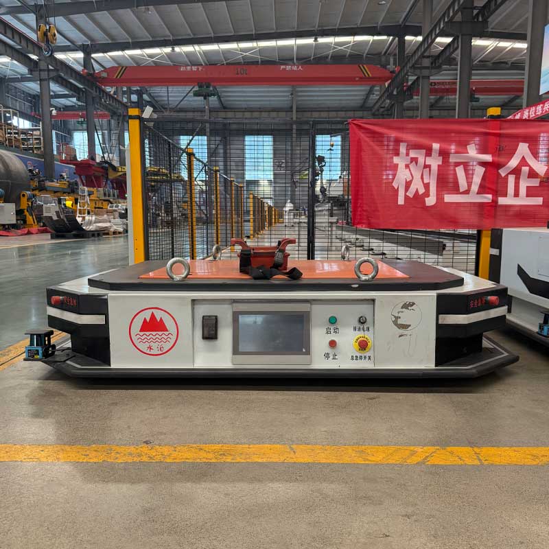
Тяговое устройство может выглядеть как относительно простое соединение автоматизированного транспортного средства с материальной тележкой, но его влияние распространяется на весь транспортный процесс. Оно определяет, насколько надежно транспортное средство соединяется с грузом, насколько плавно прицепы следуют по запланированному маршруту и насколько безопасно система останавливается, поворачивается, причаливает и выпускает транспортируемые материалы.
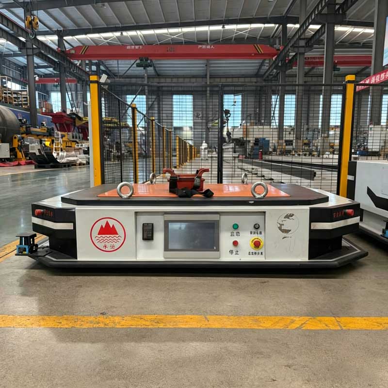
В промышленной системе AGV тяговое устройство обычно относится к механическому и управляемому сцепному узлу, используемому для соединения автоматизированного транспортного средства с одной или несколькими тележками, прицепами, приспособлениями или носителями материалов. Его можно подключать вручную, автоматически включать, поднимать на место или управлять им через центральную систему транспортного средства.
Выбор неправильной конструкции может привести к нестабильному движению прицепа, сбоям сцепки, помехам на маршруте, чрезмерному износу компонентов или небезопасному поведению при остановке. выбор правильного тягового устройства помогает превратить повторяющееся движение материала в стабильный и измеримый производственный процесс.
В этом руководстве поясняется:
- Как работает промышленное тяговое устройство
- Основные виды буксировочных соединений AGV
- Почему одного веса трейлера недостаточно для выбора
- Как расположение маршрутов влияет на эффективность тяги
- Что делает автоматическую муфту надежной
- Как тормоза, органы управления и функции безопасности должны работать вместе
- Какие пункты обслуживания заслуживают регулярного внимания
Что такое тяговое устройство в системе AGV?
Ан автоматизированное управляемое транспортное средство является мобильной системой, которая перемещает материалы по запланированным маршрутам с использованием технологий навигации, управления, зондирования и безопасности. в зависимости от своей конструкции транспортное средство может нести груз напрямую, поднимать поддон, перемещаться под носителем или тянуть один или несколько прицепов.
Тяговое устройство - это механизм соединения, используемый в окончательной конфигурации. его основная цель - передать тянущее усилие от AGV транспортируемому водилу, сохраняя при этом контролируемую механическую связь между ними.
Полное тяговое устройство может включать в себя
- Буксировочный штифт, крюк, дышло или соединительная головка
- Механизм блокировки и разблокировки
- Монтажная рама
- Датчики определения положения
- Механические направляющие
- Электрический, пневматический, гидравлический или пружинный привод
- Предохранительные блокировки
- Обратная связь о состоянии контроллера AGV
- Положения о аварийном ручном выпуске
Механизм должен более чем удерживать два компонента вместе. он должен оставаться стабильным во время разгона, торможения, прохождения поворотов, стыковки и повторных производственных циклов.
Надежная конструкция также должна четко определять состояние сцепки. Система управления должна знать, правильно ли подключен прицеп, неправильно ли он расположен, освобожден или все еще прикреплен, когда AGV получит следующую команду.
Как работает тяговое устройство
Основной принцип работы прост: AGV совмещается с прицепом, зацепляется за сцепку, подтверждает надежность соединения, транспортирует груз и отпускает его в пункте назначения.
Реальный процесс более детальный.
Подход и согласование
AGV движется к прицепу в соответствии с определенным путем стыковки. Механические направляющие, навигационные данные, датчики или визуальные маркеры помогают поместить автомобиль в допуск сцепки.
Хорошее выравнивание уменьшает боковую нагрузку на тяговое устройство. также предотвращает удар сцепного пальца или крюка о раму прицепа.
Взаимодействие муфты
Как только транспортное средство достигает правильного положения, тяговое устройство зацепляется с дышлом прицепа или точкой соединения. механизм может использовать штифт, крюк, защелку, подъемную конструкцию или узел автоматической блокировки.
Соединение не должно зависеть от неконтролируемого удара Повторное столкновение АГВ с прицепом может повредить поверхности сцепки и постепенно снизить точность позиционирования.
Подтверждение подключения
Датчик подтверждает, достиг ли механизм заблокированного положения, АГВ не должен начинать буксировку только потому, что он прибыл к ожидаемым координатам.
Позиционирование и успешное соединение - два разных условия. логика управления должна проверять оба.
Движение нагрузки
При ускорении АГВ тяговое устройство передает усилие прицепу, При поворотах муфта должна допускать требуемое угловое перемещение без чрезмерного зазора и обвязки.
Соединение также испытывает меняющиеся силы, когда прицеп пересекает стыки пола, пандусы, неровности или изогнутые маршруты.
Торможение и остановка
Во время замедления прицеп может толкать вперед AGV. Поэтому тяговое устройство должно выдерживать усилия как в тяговом, так и в сжимающем направлениях.
Характеристики остановки зависят от тормозов AGV, массы прицепа, сопротивления колес, уклона маршрута, скорости автомобиля и геометрии сцепки.
Выпустить
В пункте назначения AGV подтверждает свое положение и активирует механизм разблокировки. система должна проверить, что прицеп был отключен до того, как транспортное средство уедет.
Неполный выпуск может неожиданно перетащить прицеп или повредить сцепной узел.
Основные типы промышленных тяговых устройств
Различные приложения буксировки требуют различных методов соединения. не существует универсального тягового устройства, подходящего для каждой нагрузки, маршрута и производственной среды.
Ручная штифтовая муфта
В ручной штифтовой муфте используется съемный штифт для соединения буксировочной конструкции AGV с дышлом прицепа.
Эта конструкция механически проста и проста в проверке. может подойти, когда смена прицепа происходит нечасто или когда оператор уже участвует в погрузке и разгрузке.
Однако ручное сцепление снижает уровень автоматизации. также требуются четкие процедуры, обеспечивающие полную установку и фиксацию штифта до начала транспортировки.
Автоматическая штыревая муфта
Автоматическая штифтовая муфта совмещается с соединением прицепа и вставляет или фиксирует штифт через привод.
Это тяговое устройство подходит для выполнения повторяющихся задач по подбору и доставке, когда AGV должен работать без ручного вмешательства. датчики положения могут подтвердить, открыта ли, закрыта или заблокирована муфта.
Автоматические штыревые системы требуют более точной стыковки, чем базовые ручные соединения. дышла прицепа должны оставаться в пределах определенного диапазона высоты и положения.
Тяговое устройство крючкового типа
Крючковый механизм захватывает петлю, кольцо или дышло на прицепе. Он может использовать силу тяжести, силу пружины или привод для блокировки соединения.
Системы крючкового типа могут поддерживать быстрое соединение, но геометрия открытия должна предотвращать случайное освобождение во время поворотов, переходов пола или внезапных изменений силы.
Соединение крюка и прицепа должно быть спроектировано как согласованная пара, а не выбираться независимо.
Подъемный тяговый механизм
Подъемный механизм перемещается под частью соединения прицепа или вокруг нее и поднимает ее в надежное буксировочное положение.
Такая конфигурация может помочь автоматизировать сцепление, когда прицеп включает в себя совместимое дышло или опорную конструкцию. Это также может уменьшить необходимость точного ручного введения штифта.
Необходимо оценить ход подъема, высоту прицепа, изменение пола и баланс нагрузки. Если механизм поднимает слишком большую часть веса прицепа, это может повлиять на тягу, рулевое управление или устойчивость AGV.
Подъездной буксировочный механизм
Подъездной AGV перемещается под тележкой и зацепляется с точкой соединения снизу. Транспортное средство может поднять штифт, подъемную пластину или вращающийся механизм для фиксации тележки.
Такой подход может уменьшить внешнюю площадь буксировочной системы и может поддерживать компактные схемы мастерской Однако тележка должна обеспечивать достаточный зазор под кузовом и постоянное положение зацепления.
Обломки пола и структурные помехи также требуют внимания, поскольку муфта работает близко к земле.
Тяга и шарнирная муфта
Соединение дышла создает поворотное соединение между AGV и прицепом. Это позволяет водителю следовать за буксирующим транспортным средством через повороты.
Расположение поворота сильно влияет на отслеживание прицепа. Плохо расположенная точка сочленения может вызвать широкий угловой обрез, чрезмерное раскачивание хвоста или нестабильное поведение при движении задним ходом.
Поэтому конструкцию дышла следует оценивать вместе с маршрутом, а не как отдельный механический компонент.
Сравнение тягового устройства
| Тип тягового устройства | Лучшее приложение | Главное преимущество | Первичное ограничение | Проверка дизайна ключа |
|---|---|---|---|---|
| Ручная штифтовая муфта | Нечастые изменения трейлера | Простое строительство и проверка | Требует участия оператора | Удержание штифта и ручной доступ |
| Автоматическая штыревая муфта | Повторный беспилотный транспорт | Поддерживает автоматический самовывоз и выпуск | Требуется точная стыковка | Подтверждение и выравнивание датчика |
| Муфта крючкового типа | Быстрое подключение тележки | Быстрое вовлечение | Возможное движение внутри соединения | Геометрия крючка и безопасность блокировки |
| Подъемный тяговый механизм | Автоматизированная обработка прицепа | Сочетает в себе выравнивание и взаимодействие | Больше движущихся компонентов | Ход подъема и высота прицепа |
| Механизм захода на посадку | Компактный транспорт тележки | Использует пространство под носителем | Требуется совместимая конструкция тележки | Дорожный просвет и положение зацепления |
| Шарнирное дышло | Изогнутые буксировочные маршруты | Позволяет вращать прицеп через витки | Может увеличить стреловидность | Поворотное положение и отслеживание прицепа |
Почему буксируемого веса недостаточно для выбора
Распространенной ошибкой является выбор тягового устройства только по номинальному весу прицепа и его нагрузке Статический вес важен, но он не описывает силы, испытываемые при реальном движении.
Более полезная оценка учитывает полное состояние буксировки.
Стартовое сопротивление
AGV должен создавать достаточную силу, чтобы преодолеть сопротивление колес и начать движение прицепа. Тележка с поврежденными колесами, плотными подшипниками или смещенными роликами может потребовать гораздо большего пускового усилия, чем ухоженная тележка того же веса.
Сопротивление качению
После движения прицепа его колеса, контакт с полом, выравнивание и состояние подшипника продолжают влиять на силу, передаваемую через тяговое устройство.
Сопротивление качению может варьироваться в зависимости от условий загрузки и разгрузки. Оно также может меняться по мере износа тележек.
Ускорение
Быстрое ускорение увеличивает силу, приложенную к сцепке. плавный профиль ускорения может уменьшить ударную нагрузку, колебания прицепа и механический износ.
Самое сильное ускорение не всегда является лучшей производственной настройкой.
Градиент маршрута
Уклон увеличивает усилие, необходимое для перемещения прицепа вверх, и изменяет поведение остановки при движении вниз.
Тяговое устройство, система привода AGV и тормозная система должны оцениваться в наименее благоприятных условиях маршрута, а не только на уровне испытательного этажа.
Тормозное усилие
Во время торможения прицеп может прижиматься к тягачу Эта сжимающая нагрузка может отличаться от нормальной тянущей силы.
Соединение должно оставаться контролируемым без чрезмерного движения, ножа или удара.
Динамическое движение
Соединения пола, небольшие препятствия, повороты и неровности поверхностей могут создавать пики силы короткого времени. Муфта, выбранная только для постоянной буксировки, может испытывать преждевременный износ при повторяющихся динамических нагрузках.
Эту более широкую оценку можно охарактеризовать как диапазон тяги: полный диапазон тянущих, толкающих, угловых, вертикальных и ударных сил, которые соединение может испытывать во время производства.
Как расположение маршрутов влияет на тяговую производительность
Маршрут определяет, как двигаются AGV и прицепы как подключенная система Тяговое устройство, которое хорошо работает на прямой испытательной траектории, может вести себя по-другому в реальной мастерской.
Радиус поворота
AGV должен иметь достаточно места для поворота, не вызывая выключения прицепа за пределы допустимого угла.
Плотный изгиб может привести к контакту дышла с кузовом транспортного средства или к приложению боковой силы к сцепному штифту.
Трейлер выключен из трекинга
Прицепы не всегда следуют по точному пути AGV. Во время поворота их колеса могут двигаться внутри пути транспортного средства.
Для поездов с несколькими прицепами этот эффект может стать более значительным. при планировании маршрута следует учитывать каждый прицеп, а не только площадь AGV.
Качели хвоста
При длинном повороте прицепа его задняя часть может раскачиваться наружу Это может создать помехи для стоек, машин, колонн, защитных ограждений или пешеходных полос.
Расположение поворота тягового устройства влияет на размер этого движения.
Реверсирование
Реверс прицепа сложнее, чем тянуть его вперед Небольшие поправки на рулевое управление могут привести к большим изменениям угла наклона прицепа.
Некоторые системы буксировки должны избегать обычного обратного движения, если только AGV, геометрия прицепа, датчики и программное обеспечение управления не были специально разработаны для него.
Состояние пола
Неровные полы, деформационные швы, дренажи, пандусы и повреждения поверхности могут привести к вертикальному и горизонтальному перемещению муфты.
Тяговое устройство должно обеспечивать необходимое сочленение, не ослабляя и не нестабильно.
Ширина трассы
Ширина маршрута должна включать стреловидность AGV, сцепки, прицепа и груза. Это также должно учитывать изменение позиционирования и безопасное отделение от окружающего оборудования.
Ан Сервисный автомобиль AGV объединяет навигацию, определение безопасности, управление приводом, грузозахватные компоненты и тяговые механизмы как одну интегрированную систему транспортировки материалов. Совместная оценка этих систем более надежна, чем рассмотрение муфты как изолированного аксессуара.
Точность соединения и автоматическая стыковка
Автоматическая сцепка зависит от повторяемого выравнивания между AGV и прицепом. системе требуется достаточный допуск, чтобы справиться с нормальным изменением, но не настолько большой зазор, чтобы соединение стало нестабильным.
На точность стыковки влияет несколько факторов.
Позиция трейлера
Прицеп, размещенный под другим углом или расстоянием, может выпасть за пределы диапазона зацепления. Механические остановки или отмеченные положения парковки могут помочь сохранить согласованность.
Высота дышла
Изменения износа колес, уровня пола, нагрузки прицепа или деформации рамы могут изменить высоту сцепки.
Направляемое или плавающее тяговое устройство может выдерживать ограниченные изменения, но чрезмерные перепады высот не следует рассматривать как нормальные.
Точность навигации
AGV должен достичь точки стыковки с контролируемым положением и курсом. При конечном заходе на посадку могут использоваться пониженная скорость, локальные датчики, маркеры, отражатели или механические направляющие.
Механическое руководство
Конические направляющие могут помочь центрировать соединение прицепа перед блокировкой. направляющие поверхности должны быть спроектированы так, чтобы исправлять небольшие ошибки без создания сильного удара.
Подтверждение датчика
Надежная система может использовать более одного условия для подтверждения сцепления Например, она может проверять положение привода и наличие соединения прицепа.
Это снижает риск получения ложного сигнала блокировки при закрытии механизма без захвата прицепа.
Восстановление сбоев
Программа управления должна определить, что происходит при сбое связи. AGV может остановиться, повернуть вспять, перестроиться, попытаться выполнить ограниченную повторную попытку или запросить помощь оператора.
Повторные неконтролируемые попытки могут повредить как тяговое устройство, так и прицеп.
Требования безопасности тягового устройства
Тяговое устройство является частью системы контроля нагрузки автомобиля. Его конструкция безопасности должна охватывать как нормальную работу, так и прогнозируемые условия отказа.
Положительная блокировка
Соединение должно оставаться механически безопасным при прерывании питания Потеря электрической или пневматической энергии не должна автоматически освобождать прицеп во время движения.
Мониторинг состояния блокировки
Контроллер AGV должен получить четкий статус соединения. движение следует предотвращать, когда соединение неполное или неопределенное.
Контролируемый выпуск
Освобождение должно происходить только на утвержденной станции и при правильных условиях. AGV следует остановить, прицеп должен быть расположен безопасно, а система должна подтвердить, что выпуск разрешен.
Аварийный выпуск руководства
Техническому персоналу может потребоваться отсоединить прицеп после неисправности. Должен быть доступен метод ручного освобождения, не помещая человека под нестабильную нагрузку или между компонентами, которые могут перемещаться.
Удержание прицепа
Прицеп должен оставаться устойчивым после отпускания. на наклонных или активных производственных площадках могут потребоваться стояночные тормоза, блокировки колес, остановки пола или приспособления станции.
Защита от защемления
Автоматическая муфта создает движущиеся зазоры вокруг штифтов, крюков, дышла, и подъемные механизмы. ограждения, предупреждения, ограниченный доступ, и контролируемые рабочие последовательности могут уменьшить воздействие.
Безопасная остановка
Датчики безопасности AGV обнаруживают препятствия, но полная комбинация автомобиля и прицепа определяет, какое расстояние необходимо для остановки.
В плане безопасности должна использоваться фактическая загруженная конфигурация буксировки, а не только разгруженный AGV.
Тяговое устройство против подъемных систем и систем единичной нагрузки
Не каждая задача по транспортировке материалов требует буксировки. сравнение системных концепций может предотвратить добавление неподходящего тягового устройства в неправильное приложение.
Система тягового устройства
Буксировочный AGV тянет за собой тележки или прицепы Этот метод эффективен, когда несколько грузов можно перемещать вместе или когда существующие тележки можно адаптировать для автоматической транспортировки.
Основными инженерными проблемами являются надежность сцепки, отслеживание прицепа, ширина маршрута, торможение и согласованность тележки.
Подъемная система AGV
Подъемный AGV поднимает поддон, приспособление или держатель и напрямую поддерживает груз.
Этот подход устраняет шарнирное соединение прицепа, но требует точного выравнивания подъема, достаточной устойчивости нагрузки и совместимых несущих.
Система AGV с единичной нагрузкой
Транспортное средство с единичной загрузкой перевозит материал на платформе, конвейере, роликах или передаточном механизме.
Он подходит для доставки от рабочей станции к рабочей станции, где груз может передаваться автоматически. Транспортное средство поддерживает груз, а не буксирует его.
Правильный выбор зависит от
- Существующие материальные носители
- Требуемое количество загрузки
- Сложность маршрута
- Способ передачи
- Доступная площадь
- Стыковка рабочей станции
- Смесь продуктов
- Производственная последовательность
Тяговое устройство часто привлекательно, когда на объекте уже используются колесные тележки. Однако состояние тележки и согласованность размеров должны подходить для автоматизации.
Интеграция тягового устройства с производственным контролем
Полностью автоматизированная система буксировки требует координации между механическим оборудованием и производственным программным обеспечением.
Тяговое устройство должно взаимодействовать с контроллером AGV через четко определенные состояния, такие как
- Открытый
- Готов к паре
- Переход на позицию
- Заблокирован
- Обнаружен трейлер
- Сбой соединения
- Готов к выпуску
- Выпущен
- Виноватость
Эти состояния позволяют системе управления дорожным движением и задачами принимать более безопасные решения.
Например, AGV не должен получать транспортный маршрут до тех пор, пока не будет подтверждено соединение прицепа. В пункте назначения следующая задача не должна начинаться до тех пор, пока прицеп не будет выпущен и транспортное средство не выйдет за пределы станции.
Система может также обмениваться информацией с
- Программное обеспечение для планирования производства
- Управление складом
- Изготовление исполнительных систем
- Контроллеры рабочих станций
- Управление зарядкой
- Программное обеспечение для контроля дорожного движения
- Системы идентификации
- Контроллеры безопасности
Более широкая роль автономный управляемый автомобиль в интеллектуальном производстве заключается в том, чтобы связать движение материала с фактическим производственным ритмом. тяговое устройство поддерживает это соединение, делая прием и доставку прицепа повторяемыми.
Общие проблемы с тяговым устройством
Механизм закрывается без захвата прицепа
Обычно это указывает на неточную стыковку, чрезмерное изменение положения прицепа, неправильную высоту дышла или неполную логику датчика.
Механические направляющие и обнаружение присутствия прицепа могут повысить надежность.
Прицеп дергается, когда начинается движение
Возможные причины включают чрезмерный зазор сцепки, агрессивное ускорение, плохие колеса тележки, неровный пол или провисание соединения дышла.
Решение должно касаться всей системы буксировки, а не только снижения скорости транспортного средства.
Муфта быстро изнашивается
Несовпадение может приложить боковое усилие к штифтам, крючкам, втулкам и монтажным пластинам. Повторное воздействие во время стыковки также может увеличить износ.
Прицеп и AGV должны встречаться со сцепкой в контролируемом и центрированном положении.
Прицеп становится неустойчивым на поворотах
Маршрут может быть слишком узким, скорость может быть слишком высокой, место поворота может быть неподходящим или колесная формула прицепа может плавно не следовать за AGV.
Обзор по качающемуся пути может выявить реальную причину.
Устройство не отпускает последовательно
Это может быть результатом механической нагрузки, остающейся на муфте, загрязнения, износа привода, плохого положения прицепа или повреждения запирающего компонента.
Станция разгрузки должна позволять прицепу оставаться устойчивым, не создавая натяжения механизма.
AGV останавливается, но прицеп продолжает движение
Профиль торможения может не соответствовать загруженному условию буксировки. чрезмерный зазор дышла также может создать вторичный удар после того, как AGV начнет останавливаться.
Поведение остановки должно быть подтверждено репрезентативными нагрузками и условиями маршрута.
Техническое обслуживание и проверка
Тяговое устройство выполняет повторяющиеся механические циклы и должно включаться в профилактическое обслуживание, а не проверяться только после отказа.
Ежедневные визуальные проверки
Операторы могут искать изогнутые компоненты, незакрепленные крепежные детали, поврежденные датчики, необычный просвет, мусор или неполное движение.
Любое видимое изменение положения муфты следует исследовать до продолжения работы.
Проверка механизма блокировки
Штифты, крючки, защелки, пружины, втулки должны свободно перемещаться и достигать намеченных положений.
Износ может постепенно увеличивать зазор, даже если механизм все еще работает.
Проверка датчика
Датчики подключения должны быть проверены, чтобы подтвердить правильность сообщения об открытых, заблокированных и неисправных состояниях.
Механически безопасная муфта с неправильной обратной связью может остановить производство.Небезопасная муфта с ложным заблокированным сигналом создает более серьезный риск.
Проверка монтажной конструкции
Монтажная рама передает усилие на шасси AGV. Крепежные детали, сварные швы, кронштейны и конструктивные соединения следует проверять на предмет ослабления, деформации или усталости.
Смазка
Смазка должна соответствовать конструкции механизма и рабочей среде. Чрезмерная смазка может собирать пыль и мусор, а недостаточная смазка может увеличить трение и износ.
Осмотр со стороны прицепа
Техническое обслуживание должно включать дышло прицепа, колеса, подшипники, раму, упоры и соединительный интерфейс.
Благоустроенное тяговое устройство не может компенсировать поврежденный или непостоянный парк прицепов.
Как выбрать правильное тяговое устройство
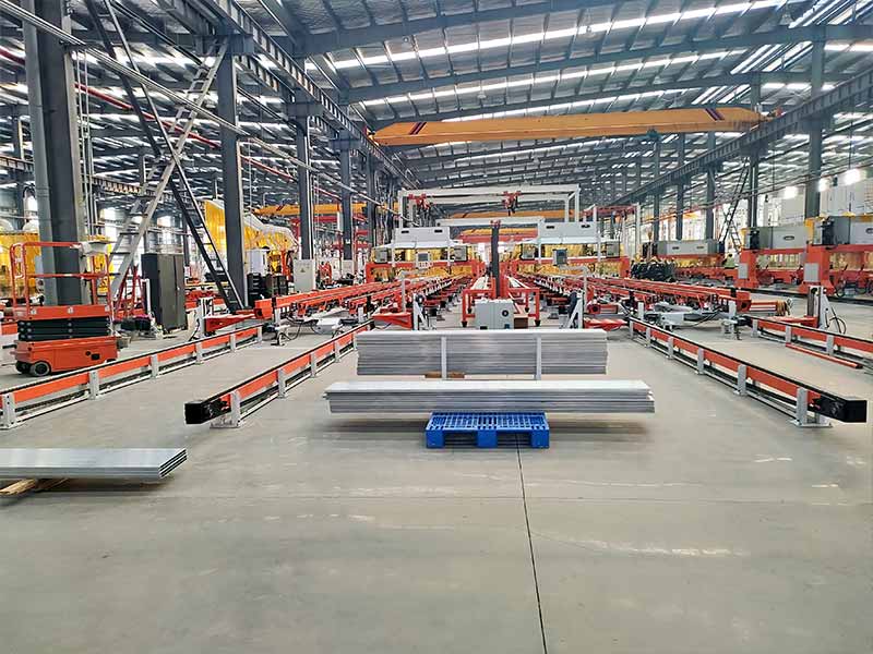
Структурированный процесс отбора снижает риск выбора механизма, основанного только на внешнем виде или номинальной нагрузке.
Шаг 1: Определите транспортную задачу
Запишите тип нагрузки, размеры тележки, количество прицепа, частоту посадки, станции доставки и необходимый уровень автоматизации.
Шаг 2: Осмотреть существующие тележки
Измерьте высоту дышла, геометрию соединения, состояние колеса, поведение при повороте, изменение размеров и устойчивость парковки.
Шаг 3: Составьте карту маршрута
Определите прямые участки, кривые, уклоны, узкие проходы, зоны стыковки, переходы перекрытий и общие рабочие зоны.
Шаг 4: Оцените динамические силы
Рассмотрим пусковое сопротивление, ускорение, торможение, уклон, удар и толкающие силы прицепа.
Шаг 5: Выберите концепцию соединения
Сравните штифт, крюк, подъем, подъезд и шарнирные конструкции в соответствии с реальной тележкой и маршрутом.
Шаг 6: Проектирование допуска на стыков
Определите, как выравнивается AGV, насколько изменчивы могут исправить механические направляющие и как обнаруживается успех соединения.
Шаг 7: Планируйте логику безопасности
Укажите поведение блокировки, блокировки движения, аварийное освобождение, удержание прицепа, условия остановки и восстановление неисправностей.
Шаг 8: Проверка с использованием производственно-репрезентативных нагрузок
Испытания должны включать нормальные нагрузки, максимальные ожидаемые нагрузки, пустые тележки, изношенные тележки, повороты, уклоны, аварийные остановки, неудачные попытки сцепления и повторные циклы захвата.
Лучшее тяговое устройство - это не обязательно самый сложный механизм, Именно конструкция стабильно соответствует транспортному средству, прицепу, маршруту, системе управления, условиям ежедневной эксплуатации.
Заключение
Тяговое устройство является важной частью автоматизированной системы буксировки, поскольку оно передает силу, управляет соединением прицепа и влияет на характеристики стыковки, поворота, остановки и спуска.
Надежный выбор требует большего, чем проверка веса прицепа Инженеры должны оценить сопротивление троганию с места, динамическую нагрузку, геометрию маршрута, торможение, выравнивание сцепки, согласованность прицепа, предохранительные блокировки и доступ к техническому обслуживанию.
Ручные штифты могут быть пригодны для простых вспомогательных операций, в то время как автоматические штифты, крюки, подъемные системы и механизмы нижнего привода поддерживают более высокий уровень автоматизации. Каждая конструкция имеет разные требования к точности стыковки, механическому наведению, подтверждению датчиков и восстановлению неисправностей.
Наиболее надежные проекты AGV рассматривают тяговое устройство как часть интегрированной системы погрузочно-разгрузочных работ. Когда сцепка, прицеп, транспортное средство, маршрут и производственные элементы управления спроектированы вместе, повторяющиеся задачи буксировки становятся более безопасными, стабильными и простыми в управлении.
ЧАСТО ЗАДАВАЕМЫЕ ВОПРОСЫ
Что такое тяговое устройство на AGV?
Тяговое устройство - это механическая муфта, которая соединяет AGV с тележкой, прицепом или носителем материала. Оно передает силы буксировки и торможения, позволяя при этом управляемое вращение. автоматические версии могут включать в себя приводы, направляющие, датчики положения, предохранительные замки и обратную связь с контроллером.
Как правильно выбрать тяговое устройство?
Начните с реальной нагрузки, конструкции прицепа, маршрута, состояния пола, радиуса поворота, уклона, и метода стыковки. Затем оцените пусковое сопротивление, тормозное усилие, допуски соединения, логику безопасности, и потребности в обслуживании. при выборе следует использовать реальные производственные тележки, а не только номинальный вес.
Может ли тяговое устройство подключаться автоматически?
Да. в автоматических системах можно использовать штифты с электроприводом, крюки, подъемные муфты или механизмы под управлением. Надежная автоматическая муфта требует повторяемого позиционирования прицепа, точной стыковки AGV, механического наведения, определения состояния замка, обнаружения прицепа и контролируемого процесса восстановления при выходе из строя.
Почему прицеп AGV во время поворотов движется боком?
Боковое движение может быть результатом смещения прицепа, неподходящей геометрии поворота, чрезмерной скорости, плохой центровки колес, плотного маршрута или слишком большого зазора сцепки. Следует оценить всю стреловидность, поскольку прицеп не всегда следует той же линии, что и буксировочный AGV.
Как часто следует проверять тяговое устройство?
Визуальное состояние и эффективность блокировки должны регулярно проверяться в рамках рутинной работы. Штифты, крючки, втулки, исполнительные механизмы, датчики, крепежные детали и интерфейсы прицепа нуждаются в плановой проверке на основе частоты цикла, условий нагрузки, износа, загрязнения и рабочей среды.